
I need a Radar Detector in this car. Only luck has kept me out of jail in the months I have been driving the Aston Martin.
I have the optional heated windshield. Note that all Radar Detector's range are somewhat compromised when mounted behind heated windshields. The small wires in the windshield interferes with the detectors range. This is not by itself reason enough not to install a radar detector. A somewhat compromised range is a lot better than no range at all.
All Radar Detectors allow you to mount these devices to the windshield via suction cups. Apart from the fact that this looks unsightly, the power cord draped across the dashboard is more than I can bear.
Unless you are installing custom detectors with front and rear antennas, the ideal location for a Radar Detector has always been below the rear view mirror. It gives unobstructed views to the front and rear antennas. I have the BlendMount Radar Detector mirror bracket (www.blendmount.com) that mounts my Valentine One to the mirror stem of my Infinity FX.
This was the location I wanted for the Aston Martin.
Unfortunately, J28 Design, the source of the BlendMount Radar Detector bracket, did not make a detector bracket for the Aston Martin. I was so impressed with the BlendMount's design that I contacted J28 Design in California about fabricating a custom Radar Detector bracket for the Aston Martin.
Even though Aston Martin's car volume pales in comparison to mainstream brands, they agreed to work with me.
To start the process, J28 Design asked me for the following measurements.
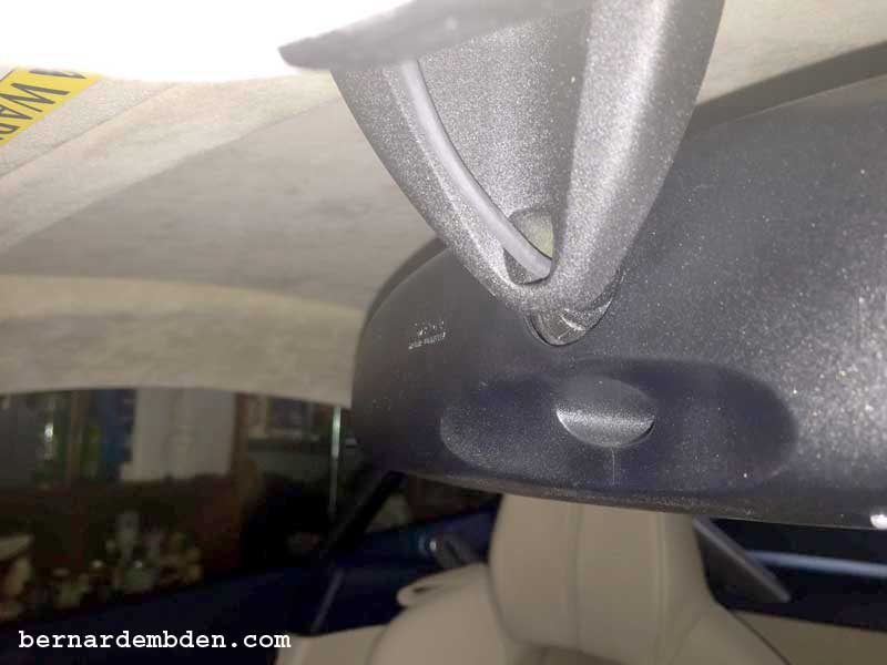
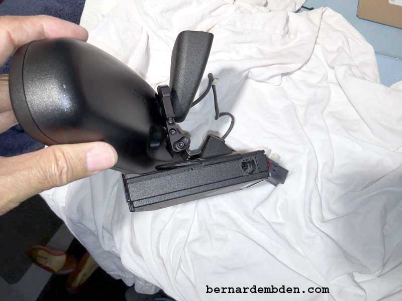
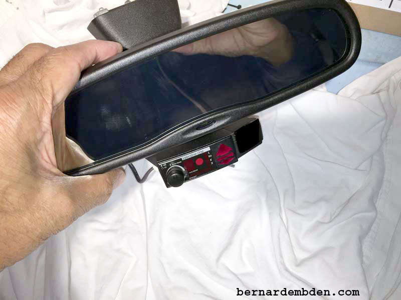
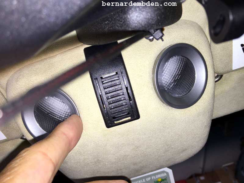
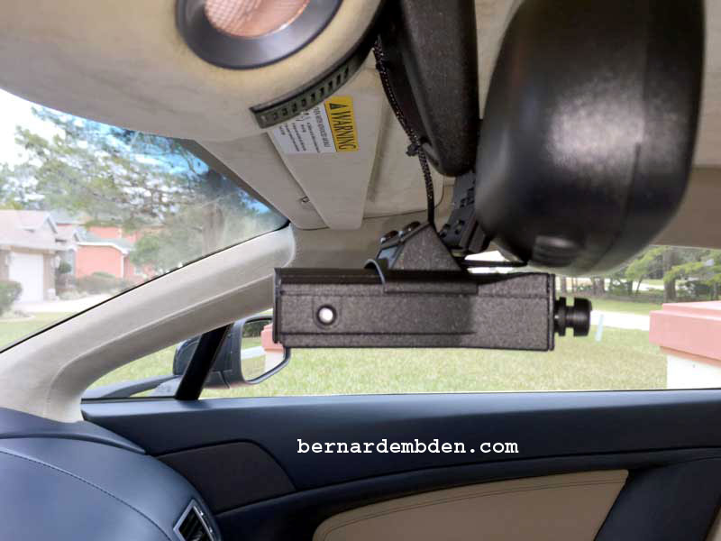
Mirror stem diameter, distance from back of mirror to mirror stem bracket, distance from mirror stem to bottom of mirror face and what kind of detector I was using. (Photographs below)
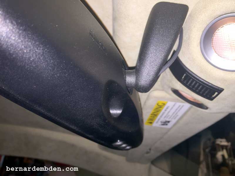
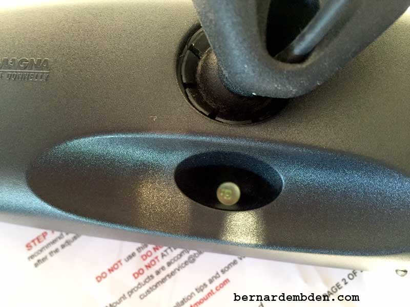
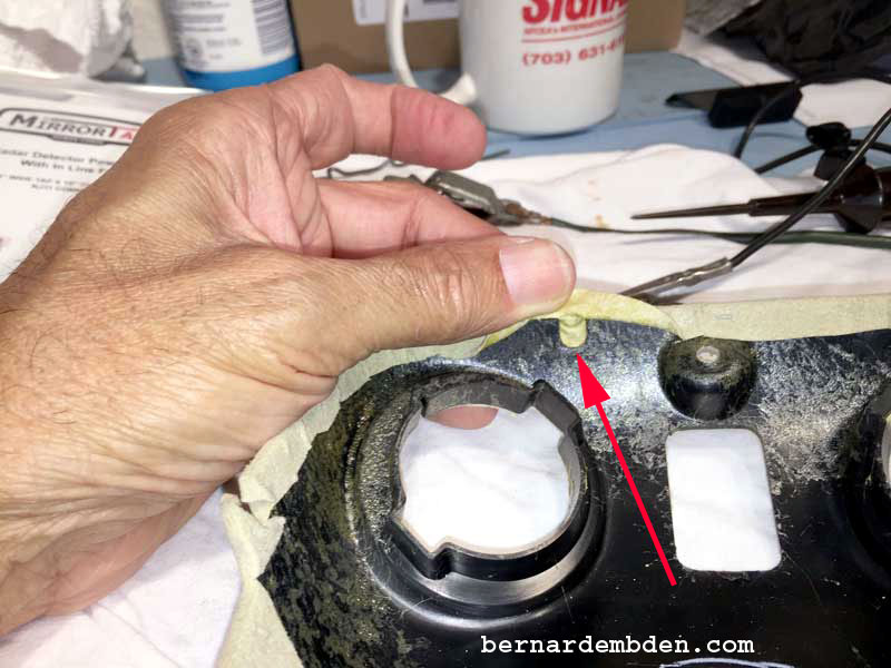
In addition, these was an ambient light sensor in the rear of the mirror that could not be completely blocked off. (Photograph below).
I am partial to the Valentine One radar detector. I know the arguments against it, Escort and other companies have passed them by, and they no longer innovate, the detector is too big; the detector is too chatty, blasé, blasé.
IMHO, The Valentine One still excels in two critical areas.
1) Range
2) Rear detection
Mark, of J28 Design, was kind enough to send me a beta mount based on my measurements. After describing and then photographing the areas where the mount did not fit properly, he sent me a second modified beta mount based on my descriptions which appeared fit properly.
The project of determining how well this mount fits, starts with removing the rear view mirror and the interior lamp pod.
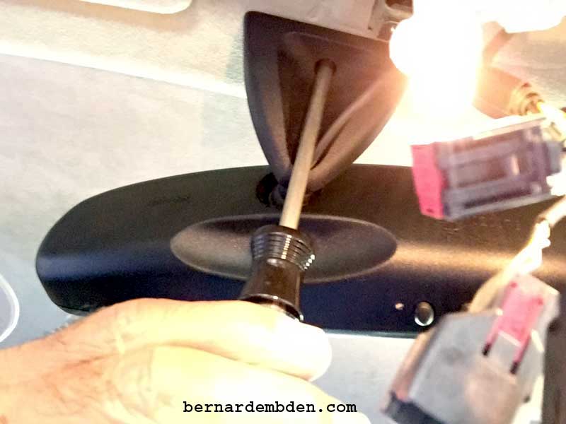
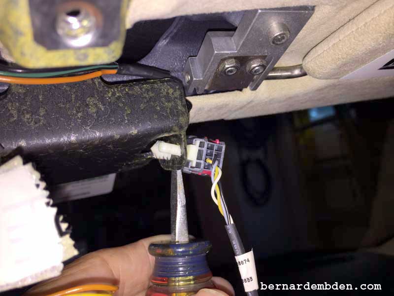
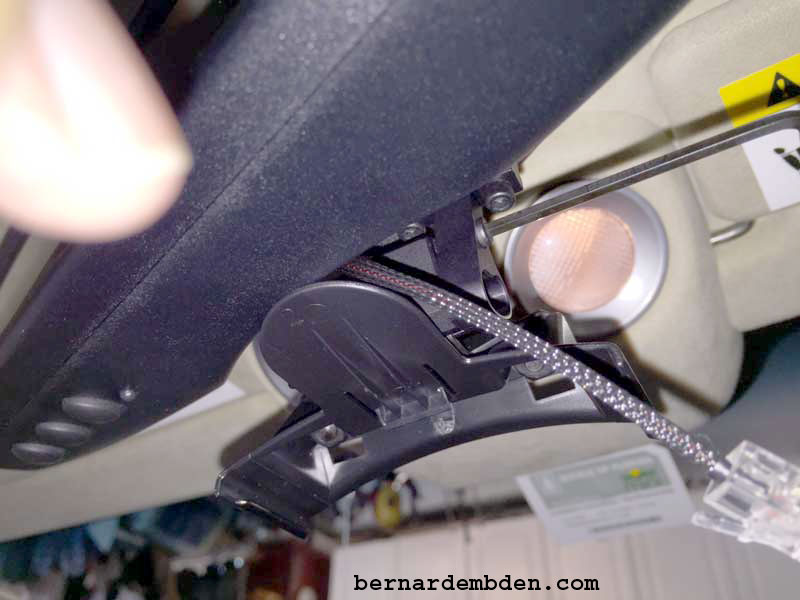
The rear view mirror's bracket has a hole thru which the wires for the microphone, HomeLink, and auto dimming functions are routed. Using a Torx 30 screwdriver remove the screw that attaches the mirror bracket to the car's header. (Photographs below)
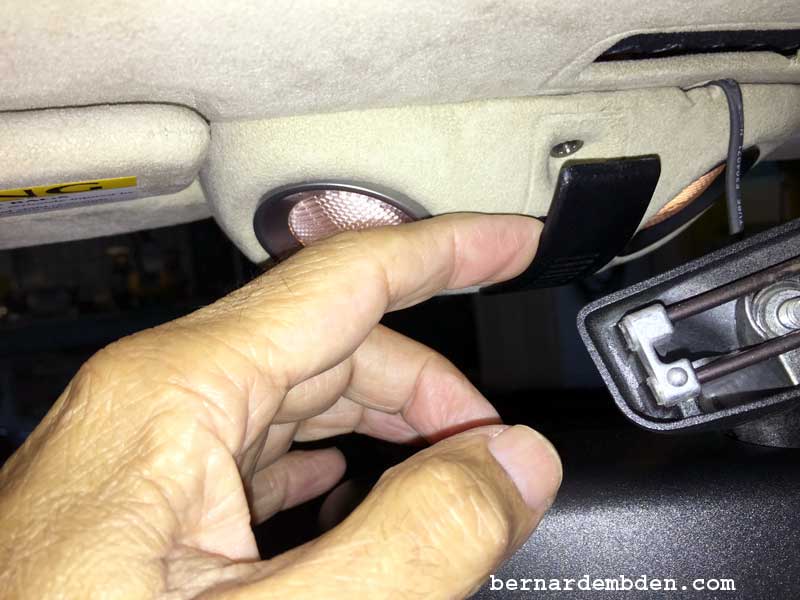
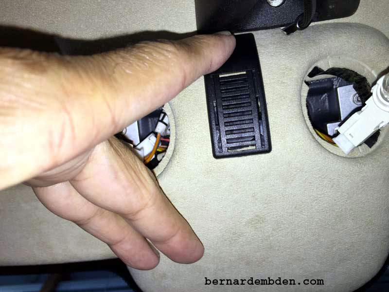
Once the mirror and bracket is removed, you have to remove to the microphone cover. It snaps into the interior light pod. Pull gently from the top (use a flat blade screwdriver if necessary). Once the top is detached gently remove the bottom. (Photograph below)
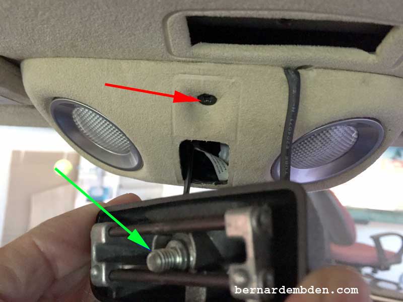
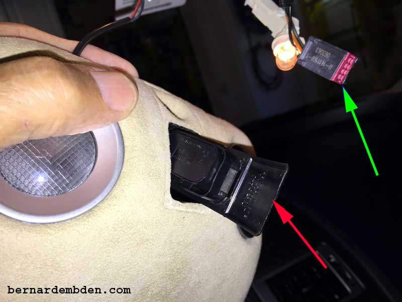
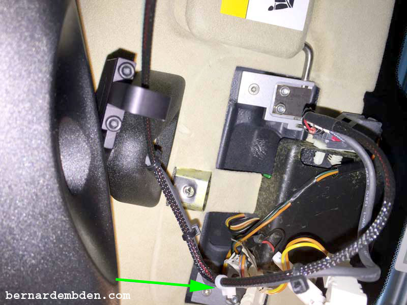
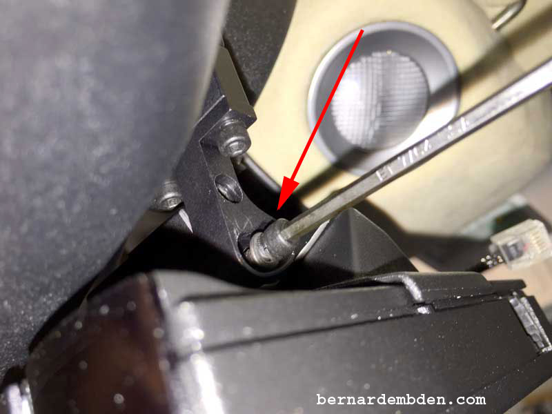
(Photograph below) Removal of the microphone cover exposes the Philips screw that holds the lamp pod to the header. (red arrow) The mirror bracket screw, held captive by the mirror bracket, is identified by the green arrow.
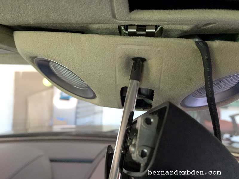
Support the mirror so it does not hang by the wires and using a Philips screwdriver remove the screw holding the interior light pod.
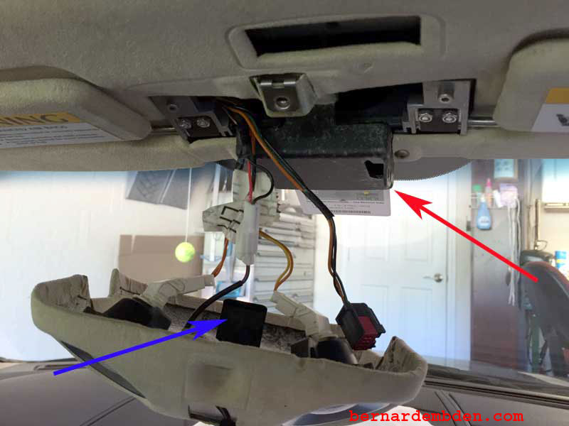
In the photograph below, the front of the light pod is attached to the header by a metal hook (blue arrow) that hooks into an attachment on the header (red arrow). Once the Philips screw is removed the light pod must be moved forward towards the windshield to un-hook the light pod assembly.
Pry the mirror wire connection from the header plastic attachment and disconnect it. (photographs below).
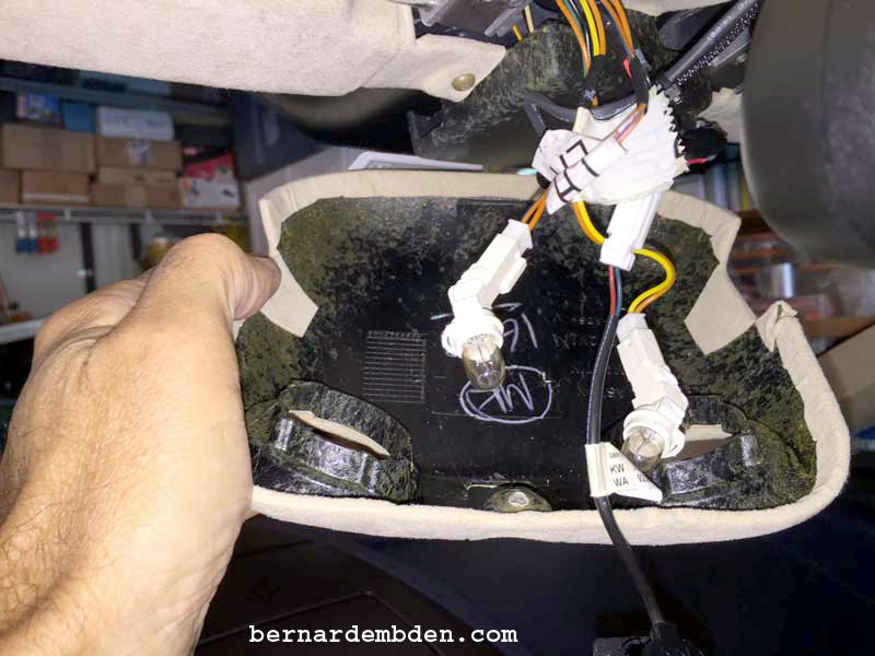
Disconnect the map lights by twisting them anticlockwise. Note the "Hook" at the front of the light pod that secured the front of the pod (red arrow photograph below) discussed prior.
(Photograph below) Remove the microphone (red arrow) from the lamp pod by turning it sideways and pushing it through the hole in the lamp pod. Blue arrow shows female mirror wire connection.
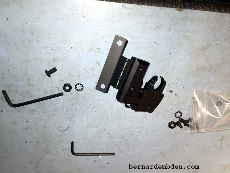
Now that the mirror, bracket and interior light pod is removed it’s time to mock-up the BlendMount beta Radar Detector bracket from J28 Design to the rear view mirror. Included with the bracket are two Allen wrenches along with two different size screws, various washers and nuts for the detector attachment.
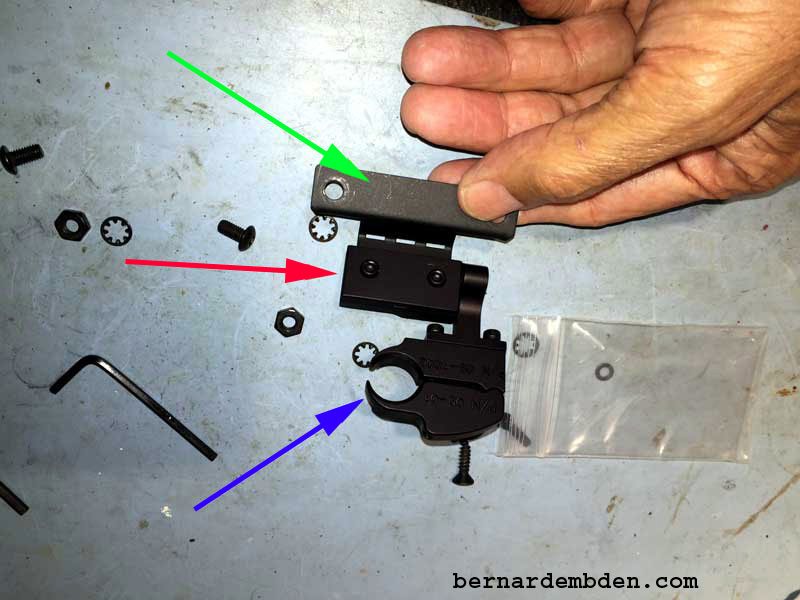
Closer examination of the BlendMount bracket shows the end that clamps to the mirror stem (blue arrow) height adjustment (red arrow) and the part that bolts to the Valentine One radar detector (green arrow),
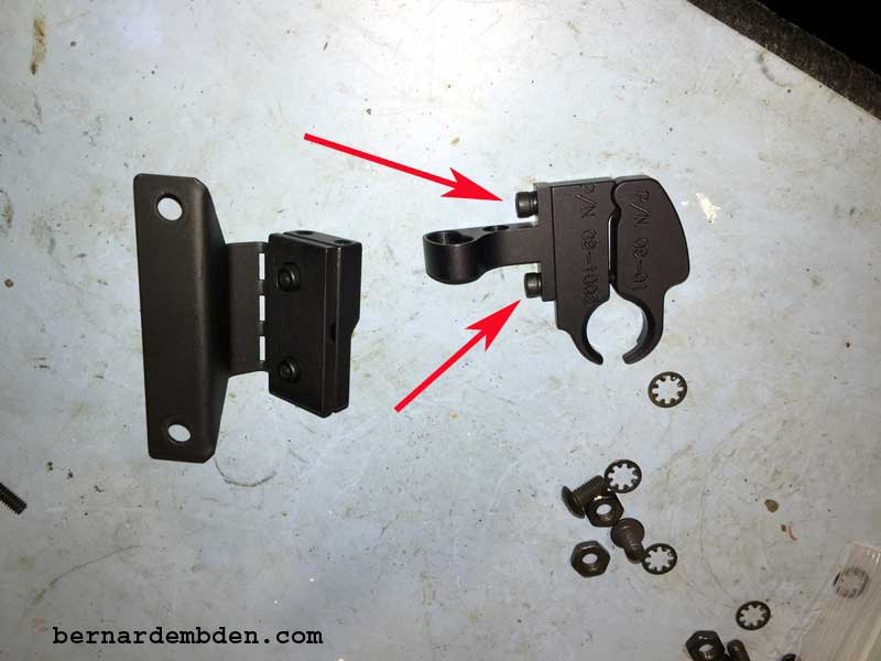
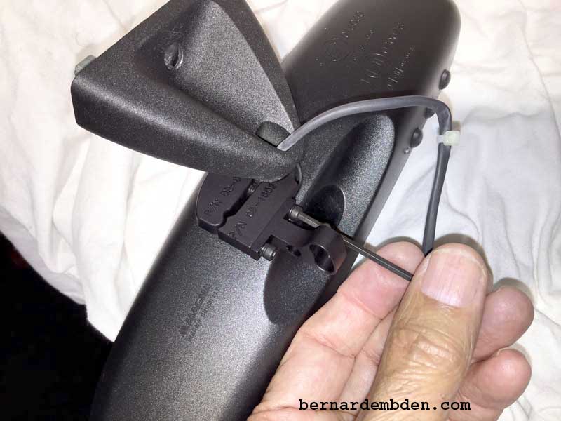
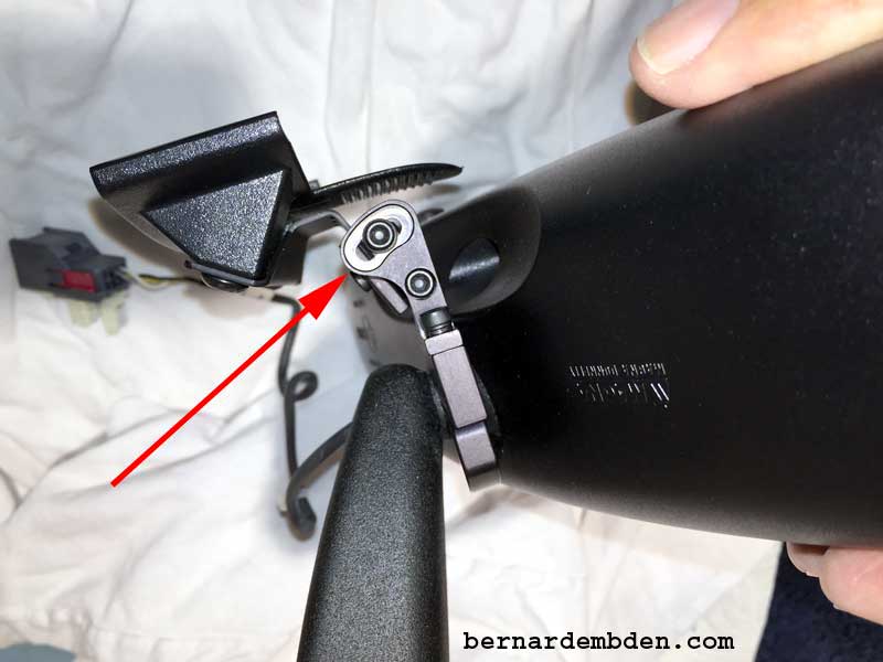
There is no access to the screws (red arrows photograph below) that tightens the bracket to the mirror stem. To install on the mirror stem the bracket has to be taken apart.
Loosen the install screw (red arrow) and fit the bracket around the mirror stem and tighten. Note that this is also the horizontal adjustment for the radar detector. (Photographs below)
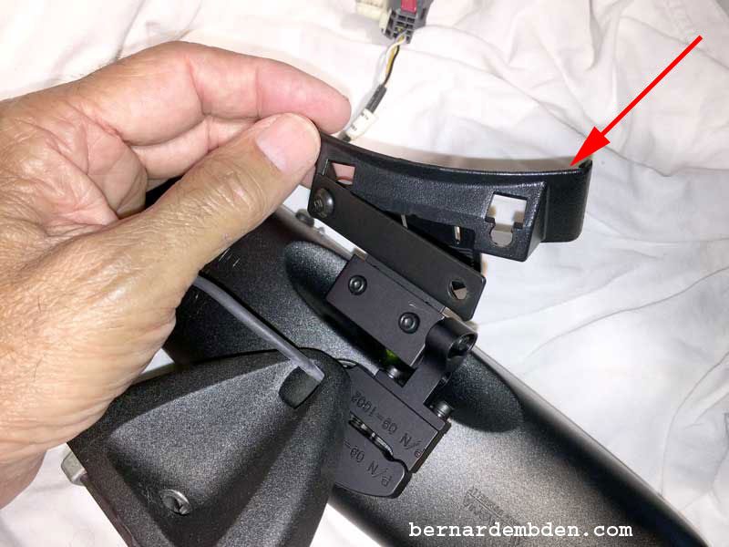
Attach height adjusting bracket to mirror stem attachment (red arrow photograph below).
Remove suction cups from detector bracket and attach detector carrying bracket (red arrow) to height adjustment of mirror mount. (Photographs below)
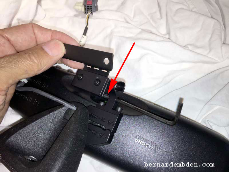
Install tilt adjusting screw (red arrow) to the mirror stem bracket. (photograph below)
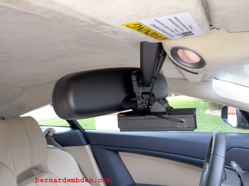
Completed BlendMount mirror bracket mock up.
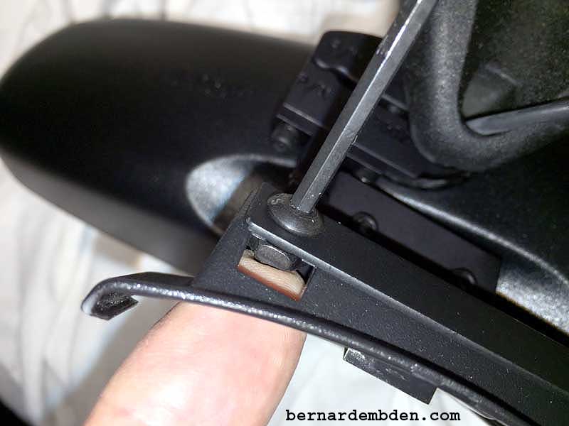
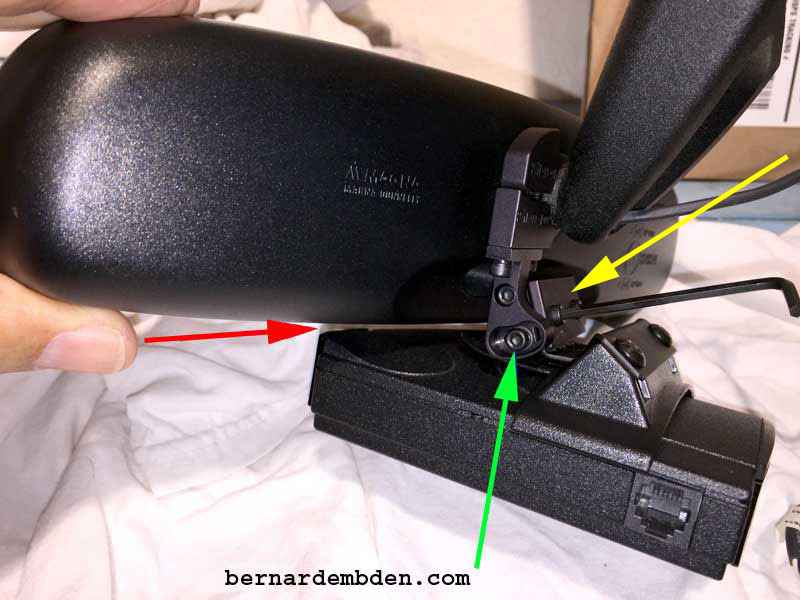
Slide radar detector into its mounting bracket. Initial mock up assembly resulted in too much space between the bottom of the mirror and the detector. (Red arrow photograph below)
(Photograph below) Use the height adjustment (yellow arrow) to move the radar detector closer to the bottom of the mirror. (red arrow) Note the bracket's tilt adjustment (green arrow).
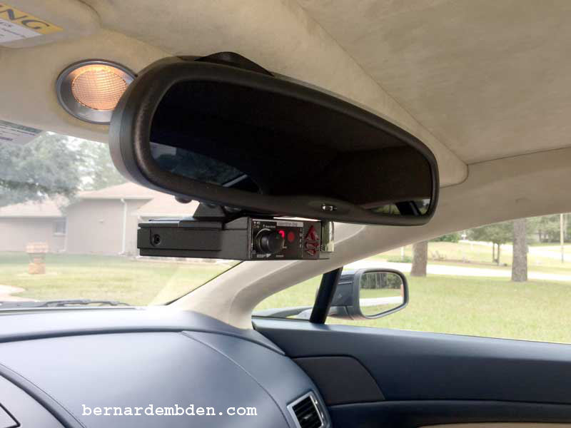
The detector is now positioned properly just below the bottom of the mirror. It can be adjusted in and out by sliding it on the bracket. How far forward or backward the detector is in relationship to the mirror face is a matter of personal preference.
The Mock Up determines that this beta version supplied by J28 Design fits perfectly, with height and tilt adjustment capabilities.
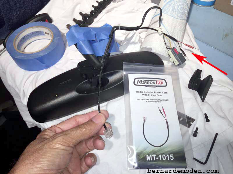
To power the detector, I purchased J28 Design's "Mirror Tap". This is a convenient way of supplying power to the radar detector from power available at the mirror wires. Note: You must have power at the mirror for this to work. If you do not have a powered mirror, Mirror Tap sells a power cable that is long enough to tap into the cars wiring harness.
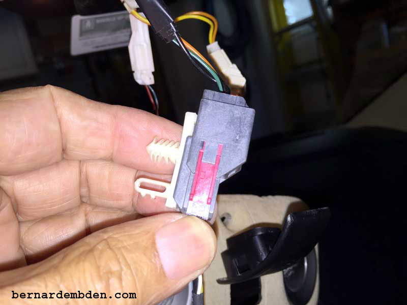
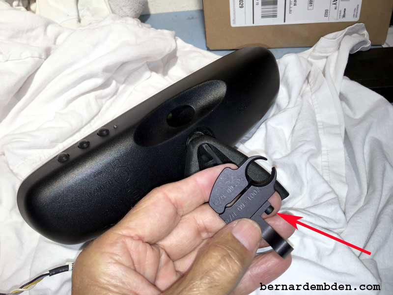
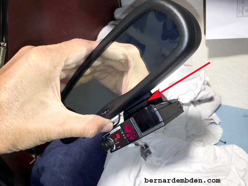
Make sure the mirror tap's wires are at least 15 inches long. The ends of the Mirror Tap's wires are connected to small "prongs". (red arrow photograph below) These are designed to push into the back of the plug, making connection easier.
I do not recommend this method. Bite the bullet and take your time to solder these connections
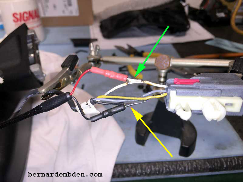
Utilizing the radar detector mock up, measure the mirror tap power cord leaving just enough to plug into the detector. (green arrow photograph below)
Select the wire harness that comes from the mirror to the plug; carefully strip the insulation from the black wire (ground) (red arrow photograph below below).
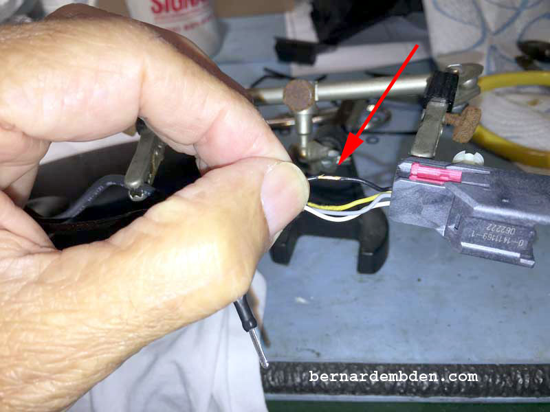
Note: The wiring harness to the plug shows power to the Home Link on the orange wire. Inexplicitly, this orange power wire transposes to the white wire after the plug.
Since I found it much more convenient to access the power between the mirror and the plug, the white wire it is. The photograph below shows the white wire's insulation stripped. (yellow arrow) Note that I did not cut the "prongs" off the wire ends of the Mirror Tap; I just soldered them to the stripped wire (green arrow).
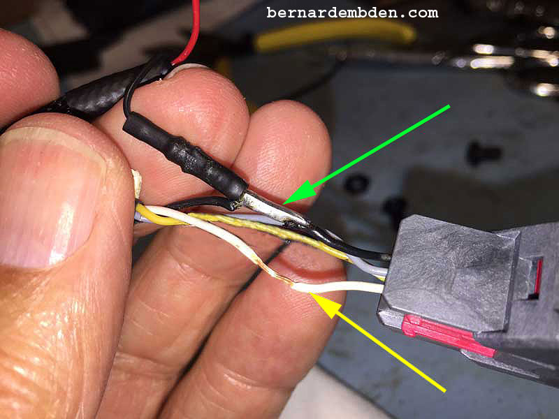
(Photographs below) Soldering complete. Positive connection is red mirror tap wire to white wire. (green arrow) Negative connection is black mirror tap wire to black wire. (yellow arrow) The connections are then taped.
With the mirror's BlendMount bracket mockup intact, there was no easy way to access the Torx 30 screw necessary to install the mirror. The height adjustment and detector bracket from the BlendMount had to be removed.
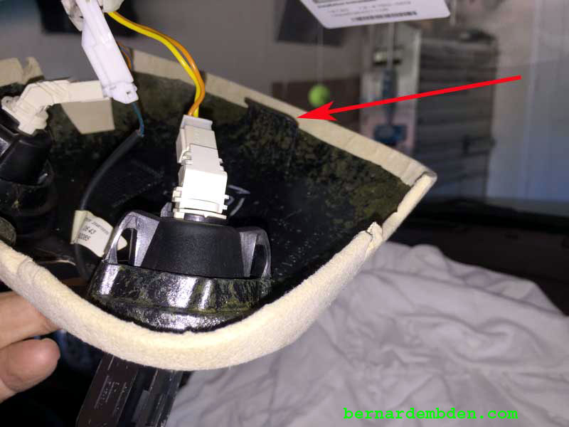
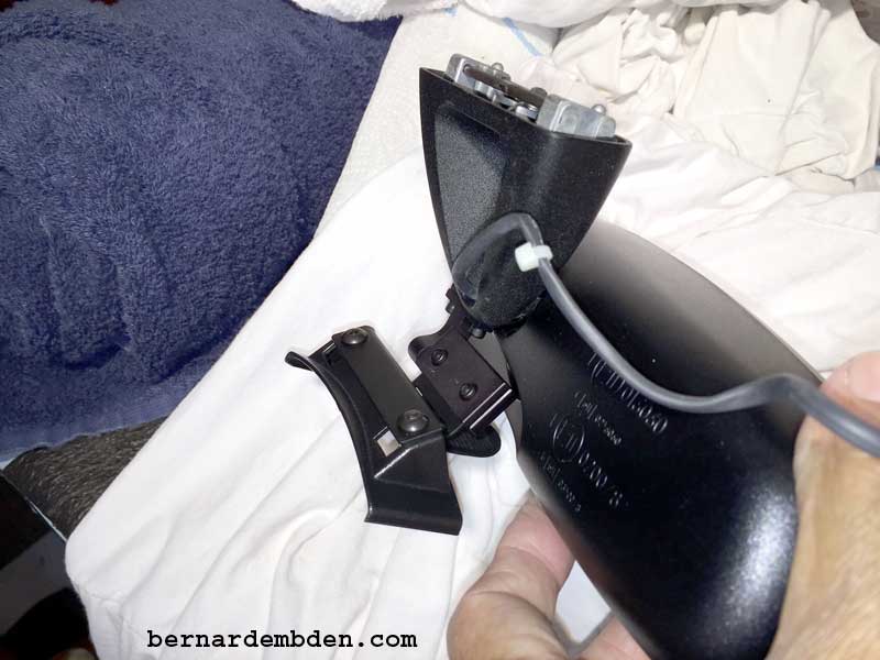
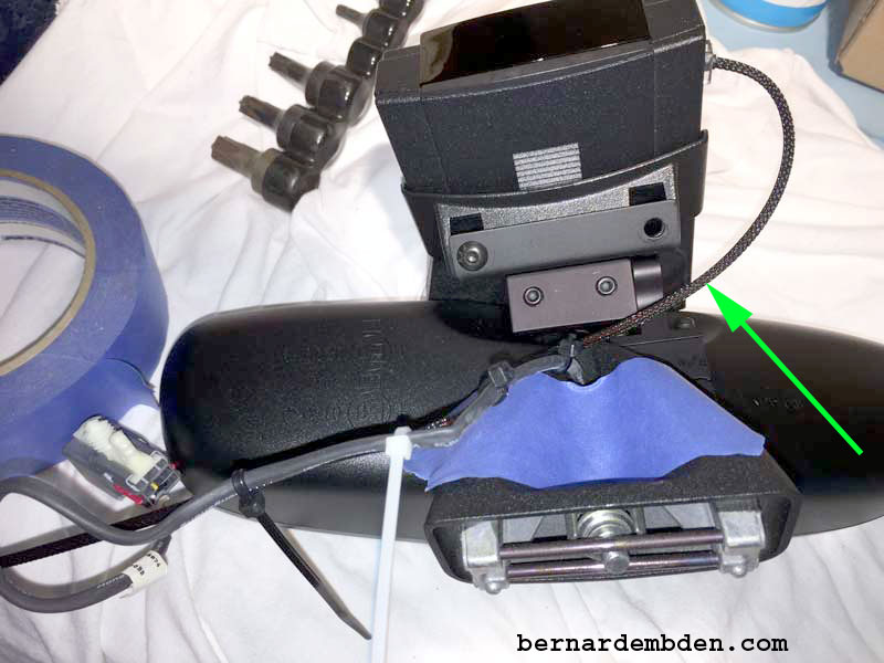
With the mirror installed note the mirror harness and Mirror Tap wires tie wrapped together. The white tie wrap (green arrow photograph below) acts as a strain relief from inside the lamp pod.
The combination of the original mirror harness and the Mirror Tap power cord means that the original relief in the lamp pod might not be enough for both wires to adequately pass through. I cut a small slit in the leather (red arrow photograph below) to allow more room for both wires.

With the wire clearance issue resolved, offer lamp pod up to windshield, making sure to engage the front clip. I found it easier to install the pod with the reading lamps removed.
Maneuver microphone through lamp pod opening. Install single Philips screw making sure that the mirror harness and Mirror Tap power wires route properly through the edge of the lamp pod. Install microphone bezel and interior lamps.
Attach height adjustment and detector bracket (removed prior necessary to install rear view mirror).
Install detector into its bracket and plug in the Mirror Tap power RJ-11 connection.
Adjust the tilt adjustment screw (red arrow photograph below) until detector is parallel to the road. Slide detector on its bracket until the front of the detector is just behind the mirror face.
Thanks to J28 Design for their help on this project. This mount should now be available as part number BV1-2029 from www.BlendMount.com.
