
I did not like my Valentine One Radar Detector attached to my vehicles windshield via suction cups.
The obvious solution has been available for some time now. Automotive enthusiasts have long determined that the ideal location for a radar detector was immediately below the existing rearview mirror, a location that allowed unrestricted visibility, forward and rearward, to the road.
Blend Mount seems to have harnessed this idea into a company which manufactures mirror attachments for a vast number of automobiles. I had one on my recently departed Infinity FX-35 and decided that my first project would be installing one on my recently acquired Porsche Macan S.
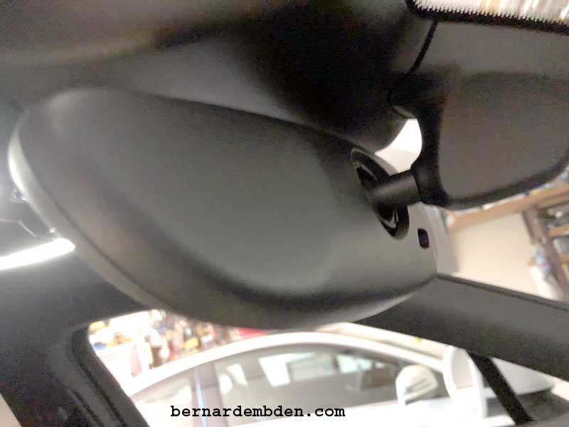
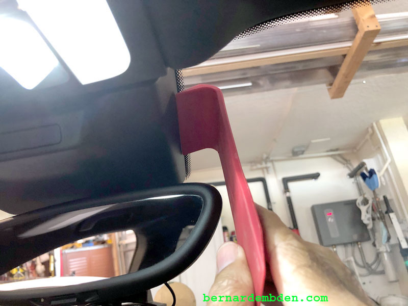
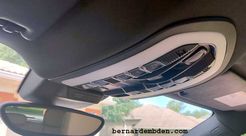
This project starts by identifying the Mirror on your car. The Mirror Mount differs on whether you have a manual mirror or automatic dimming mirror. The manual mirror has a switch stalk behind the mirror. The automatic does not. (see photograph below) Note that the Macan does not carry the Home link function on the mirror. It is located on the overhead console.
The mount was ordered for the Gen 2 Valentine Radar Detector (which had just become available). However, I intended to use my current Valentine One detector while waiting to order the Gen 2 detector. I am not sure what the differences were, but I was confident I could make it work.
The package arrived a few days later. Note that the wiring necessary to power the Radar Detector (Mirror Tap) is not included with the mount. That had to be ordered separately (from the same website and vendor). I ordered the long Mirror Tap wiring because it gave me more flexibility.
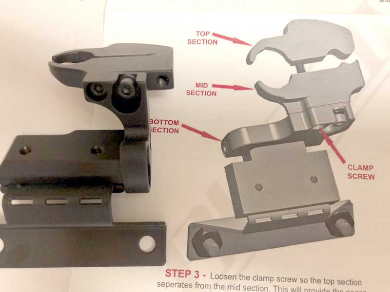
Pictured below is the mount for the Gen 2 Valentine detector along with a generic representation of the various adjustment options and the top and mid sections that mount over the mirror stem.
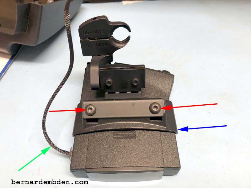
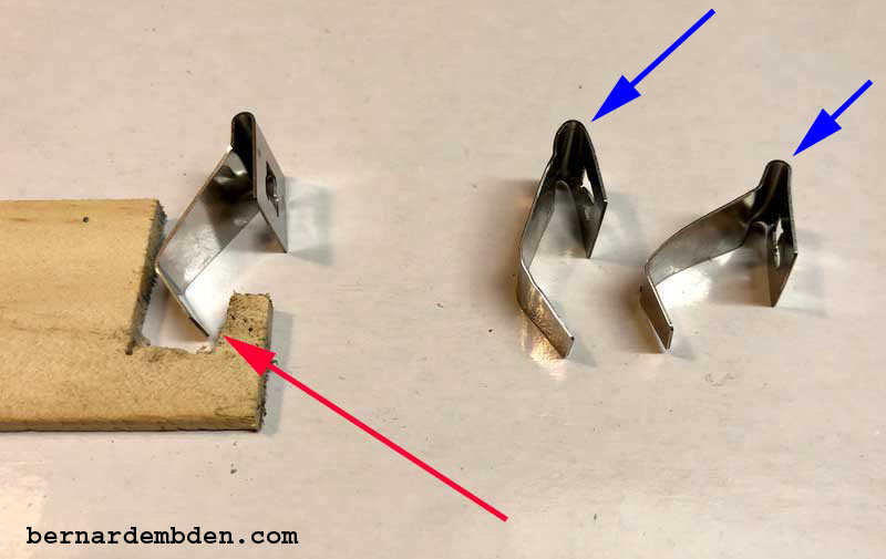
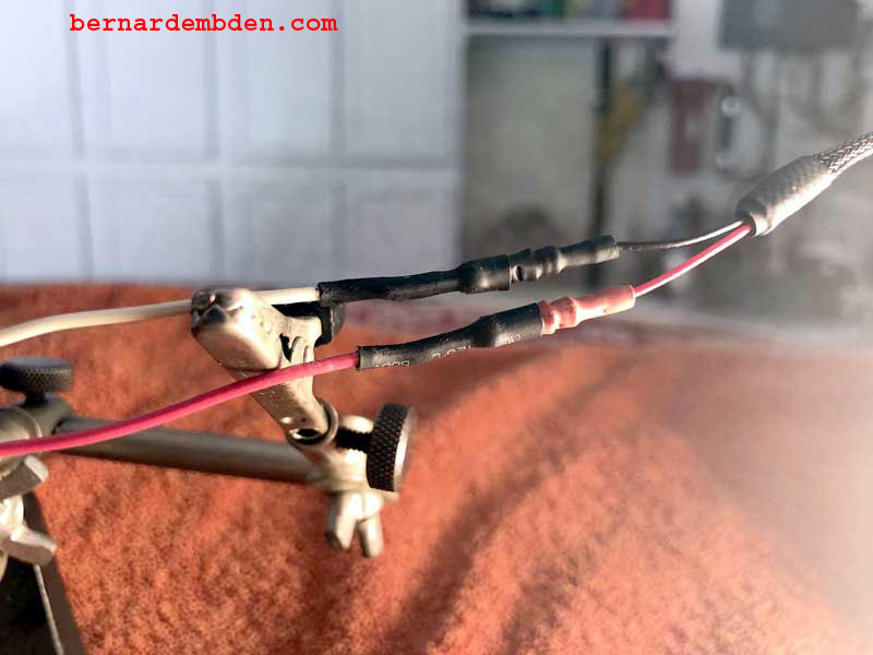
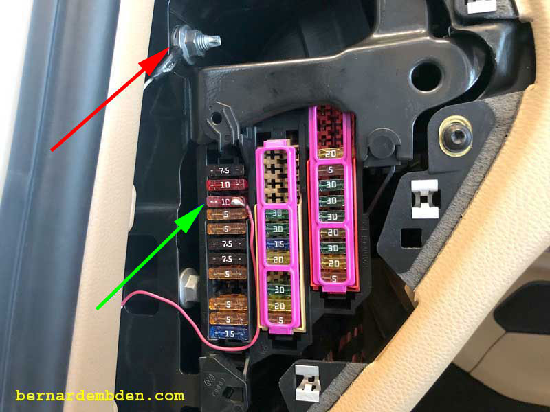
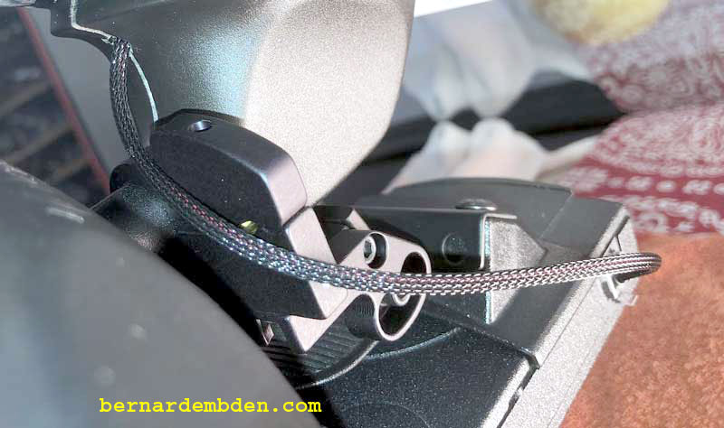
To convert the Valentine One to the Gen 2 mirror mount only required that the suction cups be removed and the bracket mounted to the Gen 2 detectors mount. (See mock up photograph below) The red arrows indicate the two nuts and bolts that secure the detector bracket (blue arrow) to the mount. The green arrow shows the mirror tap power supply cable. Note the photograph is from the rear of the detector.
In surveying the potential problems of this project, It seemed there was just no way to elegantly route (and hide) the power wire from the Radar detector up to the headliner. Invariably it seemed that a good portion of the power cable would be visible as it snaked up the side of the mirror to the headliner.
For me, that was not an option. This install needed to meet my own standards, which meant no flopping wires and or exposed connections.
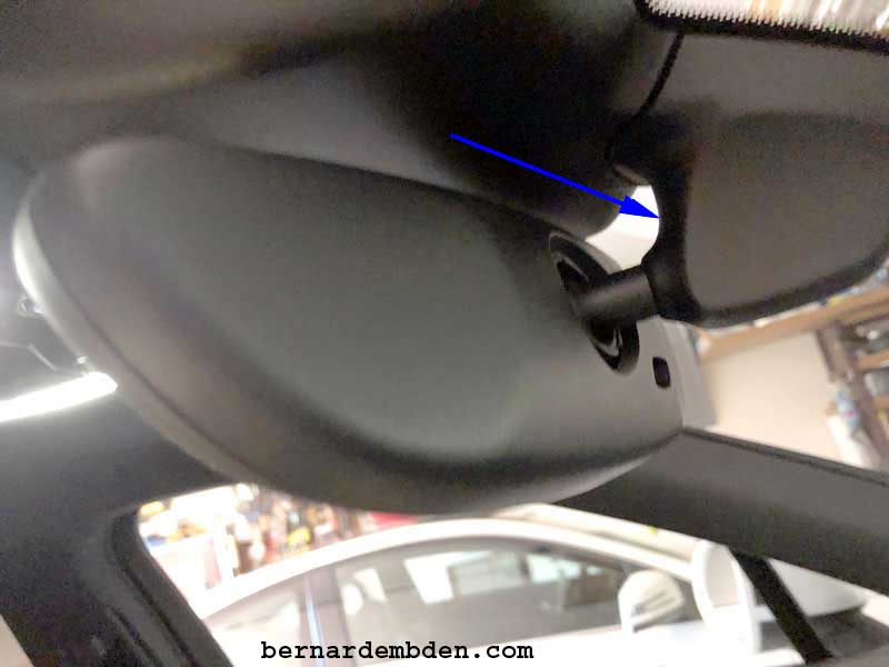
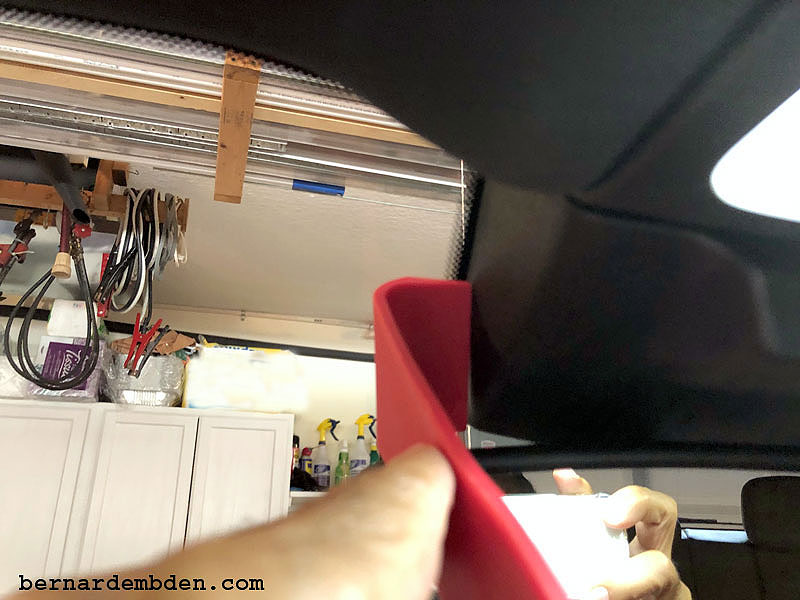
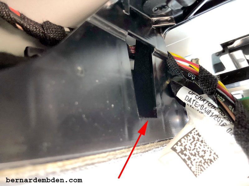
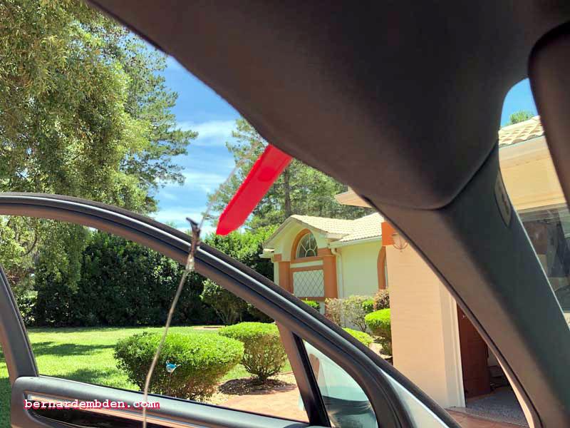
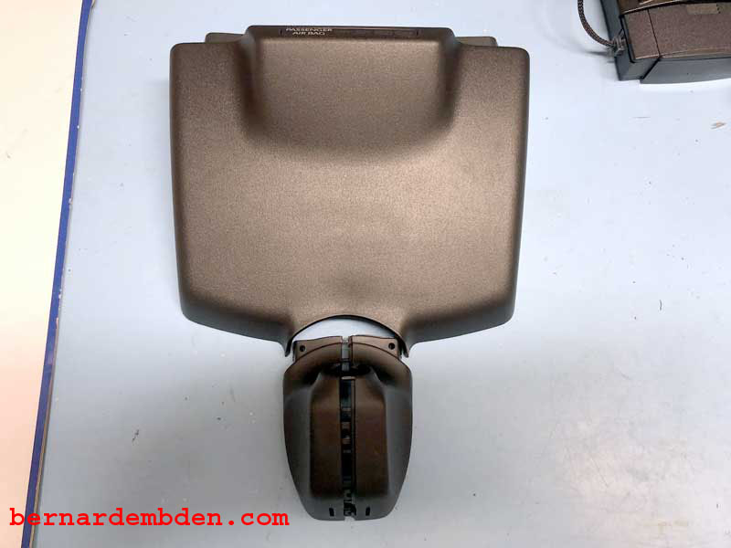
In looking at the mirror and associated sensors that adorned the Macan's windshield I decided the only logical place to exit the power cable was in the rear of the mirror's "clamshell" covering. This clamshell covers the mirror stems attachment point to the windshield glass. In addition this position was unobtrusive. If the power cable was removed, the small opening and its location would be essentially invisible. (blue arrow photograph below)
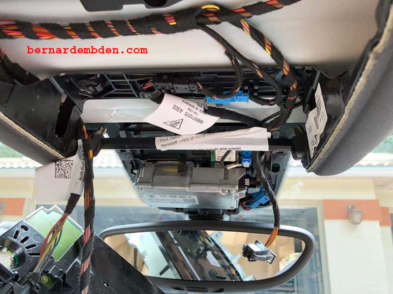
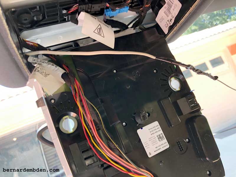
The process starts by not removing the clamshell, but removing the sensor array covering above the clamshell. This would determine the feasibility of bridging on to the mirror power wires. (Photographs below)
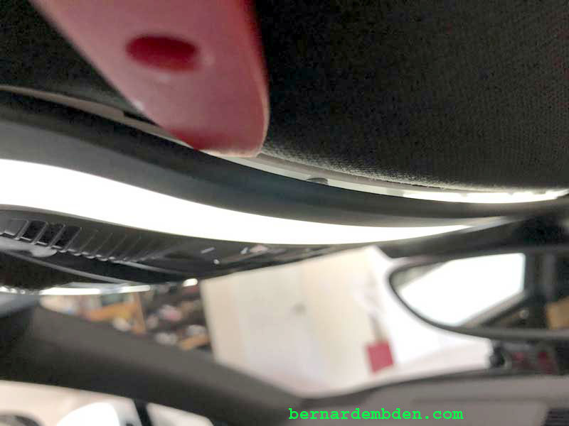
The sensor array cover could not be completely removed without removing the mirror. However there was enough clearance to see behind it and it was not a pretty sight.
There was no room to gain access to the wires that powered the mirror. The mirror was powered by a cable that was routed behind the large sensor assembly. I needed power for the Radar detector but it was impossible to be sourced at this location.
The overhead console had to be removed.
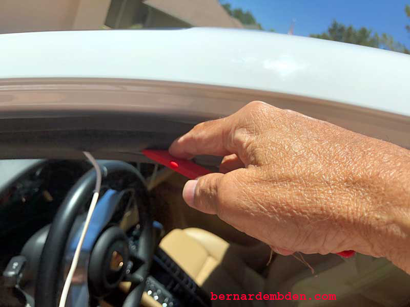
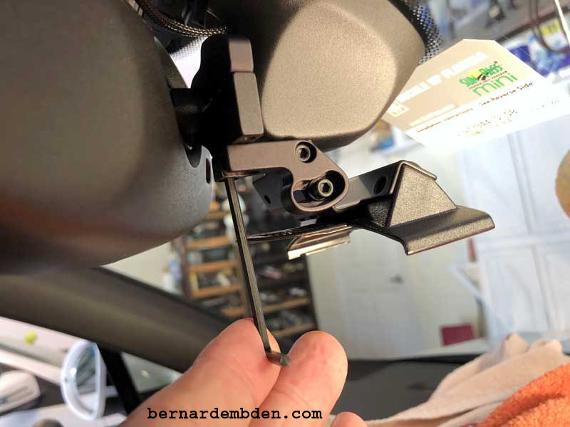
A trim removal tool is used to gently separate the outside trim from its housing. Tread carefully here as the tabs are fragile. (see photograph below)
(Note: The second photograph below is for reference only, as it does not show the trim removed)
Nothing happened. Nada, zip. The plastic removal trim tool bent in submission and became useless. I resorted to madness and broke out a large screwdriver and leaned on it in a highly inappropriate fashion and still the overhead console refused to move one iota.
Based on the workshop manual the overhead console should pop out obediently with minimal but firm pressure of the trim removal tool.
This is where you are going to need alcohol, and probably in large quantities.
Using the large trim tool to protect the headliner and my big boy screwdriver I decided to treat this vehicle as if I rented it, as opposed to paying a significantly large sum of dineros for it. Yes I leaned on the screwdriver as if I was in a hurry at the junkyard and with a frightening sound the overhead console came out, slightly, maybe an inch, or inch and a half..
I could see that the sides were held in by plastic tabs that could be squeezed in, which released the console by another half inch. Now fully in my junkyard mentally
I just ripped the damm thing out.
One retaining clip just flat out disappeared into the ozone layer. I heard a noise is it buzzed by me and hit somewhere inside the car and then magically vanished. Without one clip reinstalling the upper console would be impossible, so I resorted to my secret weapon to find anything that is lost.
My Wife.
She can find anything. But even with her super powers the clip remained in a parallel universe, lost forever.
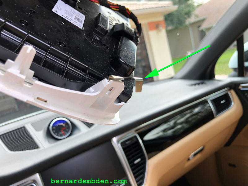
Once the console was removed the reason for its reluctance became visible. The photographs below identify mangled front and rear clips (green arrows).
At this point the sensor cover can be removed after removing the passenger airbag light plug. (green arrow photograph below). Note sensor assemblies on windshield. (second photograph below).
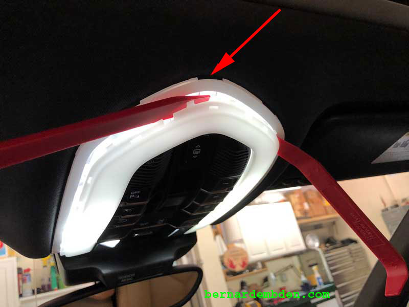
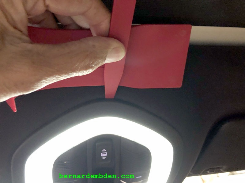
Examination of the retaining clips that hold the overhead console up identified the problem. These clips are designed to be compressed during installation and then uncompressed and expand into openings within the plastic surround installed in the roof. (red arrow photograph below)
Therein lies the problem.
There is at best a 1/8 inch clearance between the console body and the roof opening it is designed to be installed into. Once the clips have expanded into the corresponding openings in the overhead console surround there is no room and therefore no way to re-compress them to release the console. Now, a properly designed clip would re-compress when the console was being removed.
This is not a properly designed clip. When the console is installed and the clips expand, the bottom of some clips can extend over the lip of the opening in the plastic surround in the roof. Essentially, even if you had access via the 1/8 inch clearance there is no way to compress the clips so the console can be removed.
By pulling down on the overhead console you are digging your own grave (or the clips grave) as the bottom of the clips, now behind the plastic lip that they are uncompressed into, will not release them until they are bent and deformed.
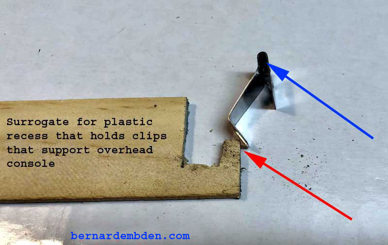
In the series of photographs below the scrap wood represents the plastic recess that the clips expand into to hold the overhead console. The blue arrow shows the area of the clip that attaches to the overhead console. The red arrow (photograph below) shows the ideal position of the clip as it relates to the plastic recess. Note that this is a new clip.
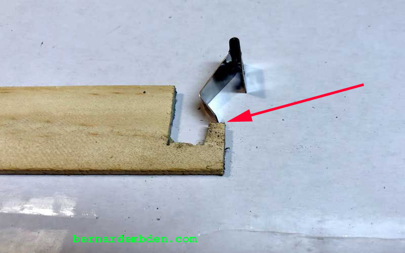
The problem is that the design of the clip leaves no room for real world variances. In pushing the console firmly into its opening in order to reinstall it back into the roof, the process invariably compress the headliner somewhat. The result is disaster because the bottom of the clip can travel beyond its target area and expands to sit on top of the plastic lip (red arrow photograph below).
(photograph below) In a worst case scenario the tip of the clip expands and gets trapped behind the lip that is supposed to hold it. (red arrow). Blue arrows show the mangled clips. In either of these cases the clip is doomed and cannot be removed without destroying them.
Finally, you might think that fixing the clips and reinstalling the console will work. The answer is "maybe". If you can accurately replicate the angle of the clips, using the new clip in the above photographs then there is a reasonable expectation that they will work. If they are not duplicated fairly accurately then the console might not hold or be too loose in the opening.
Is there a foolproof solution for properly reinstalling the roof console? Yes, purchase new clips before you start this project.
The part number is 95B868771 and you will need four.
If you are purchasing from the Porsche dealer you will also need to be sitting down when you place your order.
At this point I had no choice. Having lost one clip it was now necessary for me to interface with the Death Star (Porsche dealer).
I called the Porsche dealer and ordered four clips, (part number 5B868771). I asked how much the cost would be.His reply was "$21 dollars and some cents".
I replied "OK".
He replied "Each"
I asked him "Each what"
He replied "Each clip".
I asked him if he was stuttering.
He said no, they were $21 dollars US (and some cents, I was in shock so I don t remember exactly) each. and they had to be ordered, would take a few days. Did I want to order them?
I said "No thank you" and hung up.
I own an Aston Martin, I know what excessive markup on parts is. I must grudgingly congratulate Porsche; they have reset the bar and has taken it to a whole new level.
The sad part is that if the dealer had the clips in stock I would have bought them (smile).
A web search determined that suncoastparts.com, mail order for Porsche and accessories, sells the clips for less that $7 dollars each.
I ordered five, you know just in case one disappeared again.
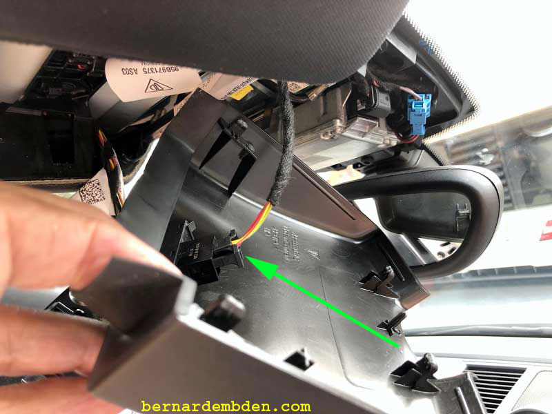
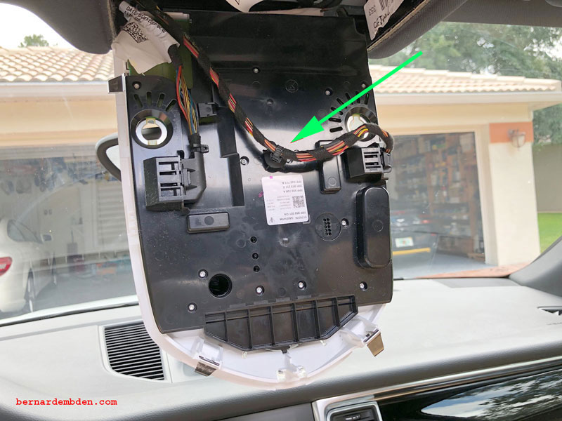
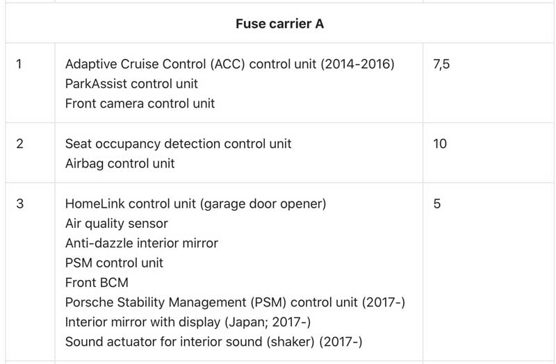
With the overhead console removed you will have access to the wires that power the Home Link system (green arrow photograph below). As noted earlier, the Home Link (garage door opener) is activated not from the mirror, but via the overhead console and is the ideal source for powering the radar detector as that circuit is powered on and off with the ignition switch.
You will a need multi meter to identify the ground and power wires that operates the Home Link circuit, which is activated from a button on the overhead console, and for most people this will be the power source.
But I was having second thoughts. First there was a possibility that power could not be sources at the above wires. I did not have a wiring diagram, however it’s possible that the overhead console garage door button only "signals" the computer, which then activates the garage door opener.
This far into the project, with the overhead console removed, I decided to pick up power at the fuse box, specifically the fuse box at the drivers side of the dash that houses the Home link fuse panel.
The reason was simple. I wanted total control over the power source along with a dedicated fuse just for the Radar Detector. If I bridged onto the Home link power source at the upper console I would be permanently tied into that circuit and that fuse. I wanted separate fuses.
Need to run some wires.
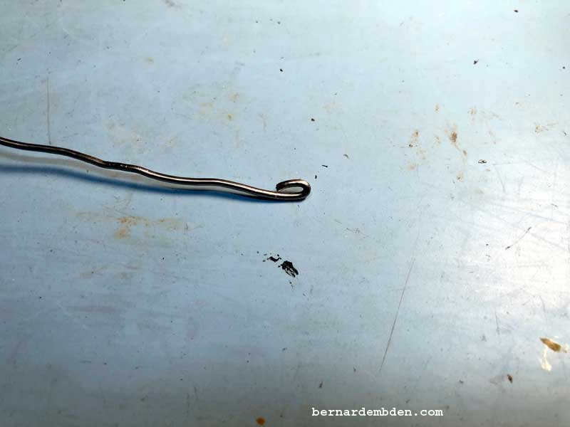
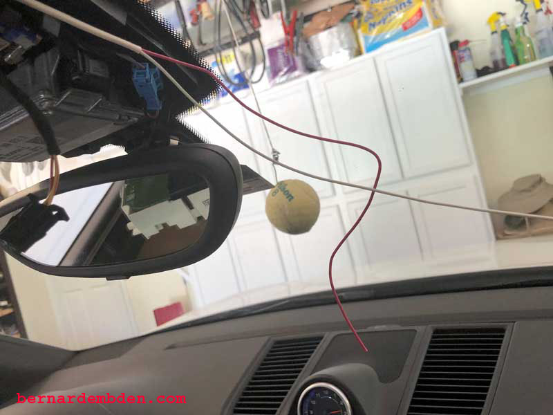
With the overhead console removed I used a stiff wire to snake from the trim above the driver s door to the console opening. I found it easier to snake from over the driver s door to the console opening because that opening is quite large and will allow you to easily find the end of the snake. Note: Round off the end of any wire being used for a snake. This will avoid going through your headliner. (photograph below)
Attach the wire that will be used to power the detector to the snake and drag through to the console opening.
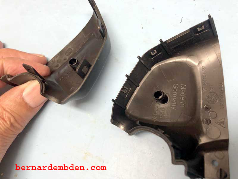
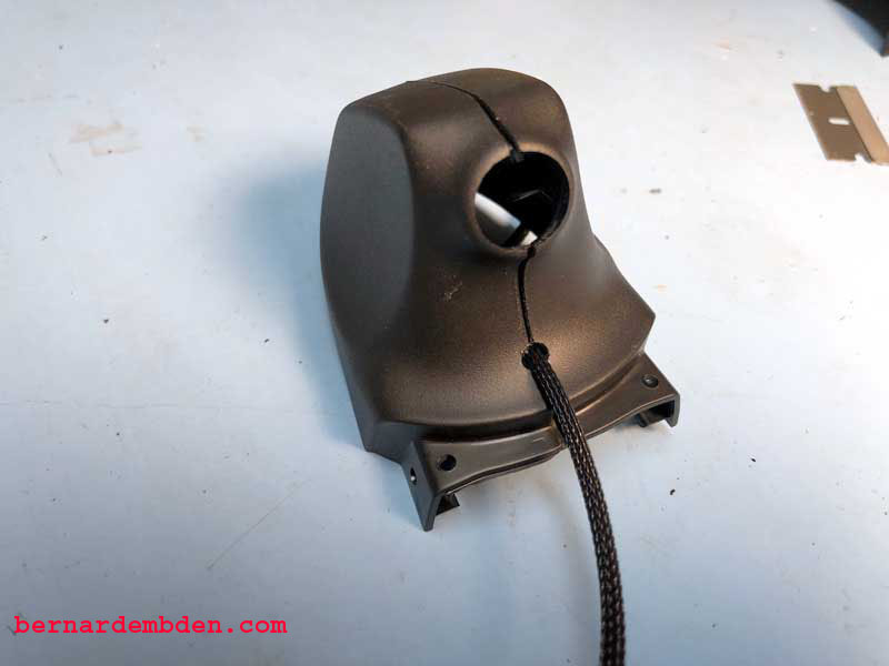
The Radar detector will be powered with a cable exiting from the top of the clamshell that surrounds the rear view mirror attachment point at the windshield. The clamshell is removed by splitting it apart at the front just above the mirror stalk. The photographs below shows the clamshell open. Rear of the clamshell closed and the clamshell and sensor cover as they would be installed on the windshield
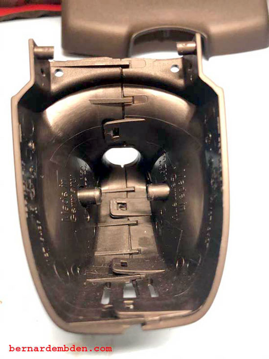
With the clamshell closed, a small hole is drilled in the center of the top as it would be installed on the windshield, just big enough for the Radar detector mirror tap power cable to pass through. (photograph below)
(photograph below).The wire from the console is then routed close to the windshield sensor array on to the dashboard to facilitate soldering to the mirror tap power cable.
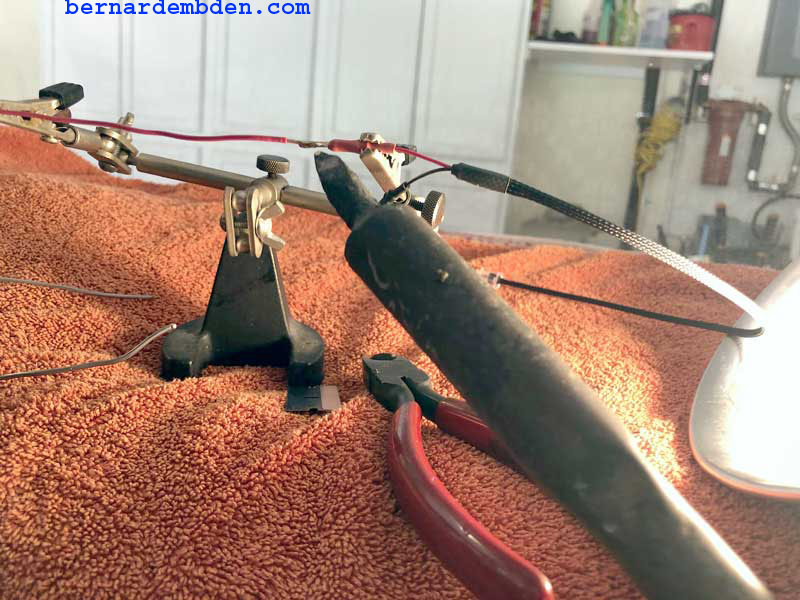
After protecting the dash, solder the cable to the mirror tap making sure to observe polarity. Finish using the appropriate size heat shrink tubing. (photographs below)
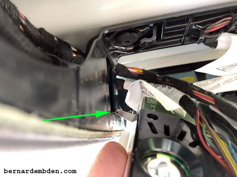
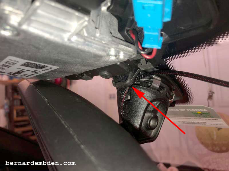
Routing these wires was always going to be a bitch. However I was confident that there was a narrow path that would exit at the clamshell top location. Start by placing the clamshell around the power wire cable and snapping it closed around the rear view mirror attachment point in the windshield. The cable must pass between the clamshell and the hard plastic mounting point. (red arrow photograph below).
Do a quick check now by holding the detector attached to the Blend Mount next to the mirror stem. You need to make sure that you have enough power mirror tap cable to plug into the Radar detector. (You cannot pull slack afterwards)
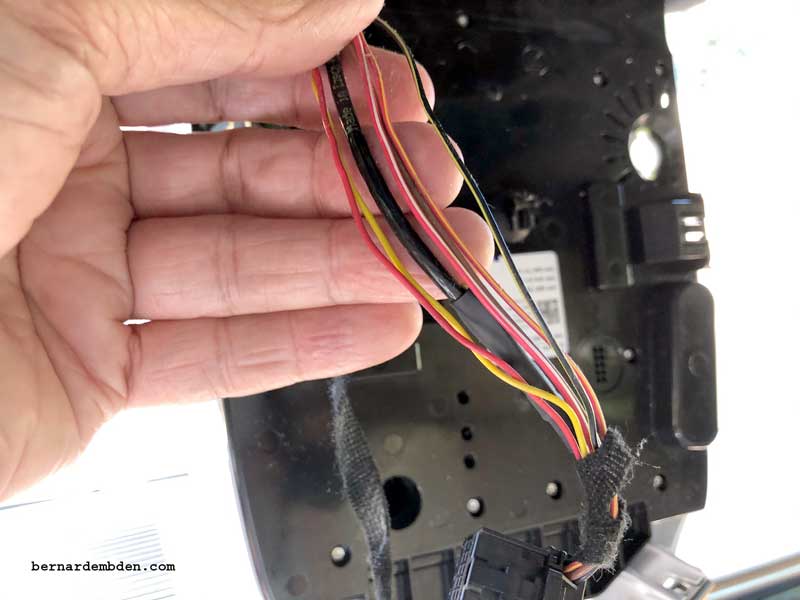
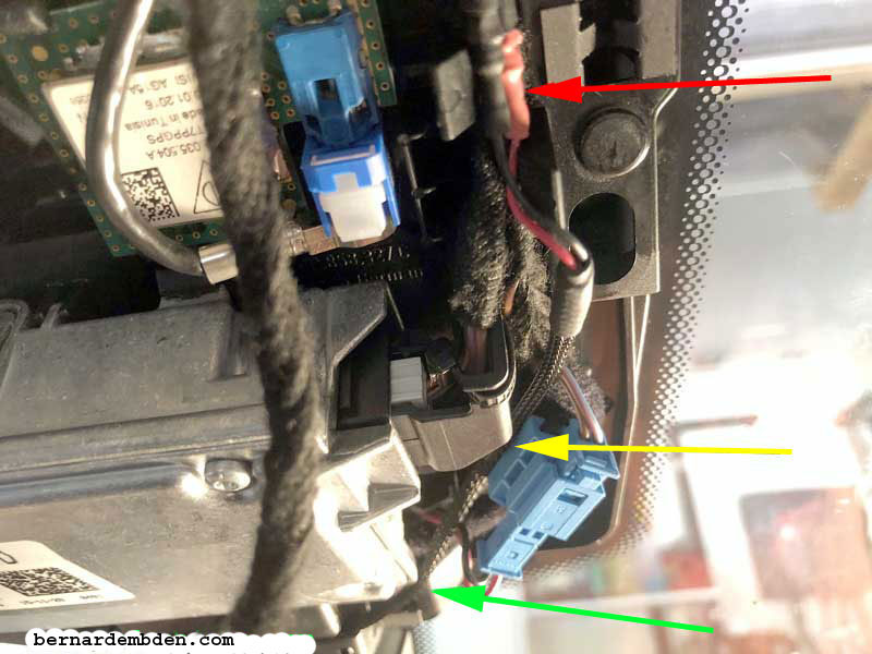
This next step is critical. The wire must be routed exactly as shown in the photograph below. The red arrow indicates the soldered attachment of the mirror tap to the new power cable. The yellow and green arrows indicate where the mirror tap cable must go. Around and tight to the bottom of the sensor box (green arrow) and between the blue connection and sensor body. (yellow arrow).
Do it right and the plastic sensor array cover will snap back into its retaining clips. If it does not, remove sensor array cover and check wire routing.
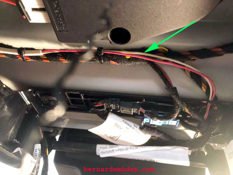
With the clamshell and sensor array covers on, use tie wraps to secure the new Radar detector power cable (green arrow photograph below) to the existing cable at the top of the console's opening.
Using a trim tool, lift the rubber weather stripping from the door channel and tuck the power cable underneath it. Work your way down the door opening and exit inside the driver side fuse panel. (photographs below)
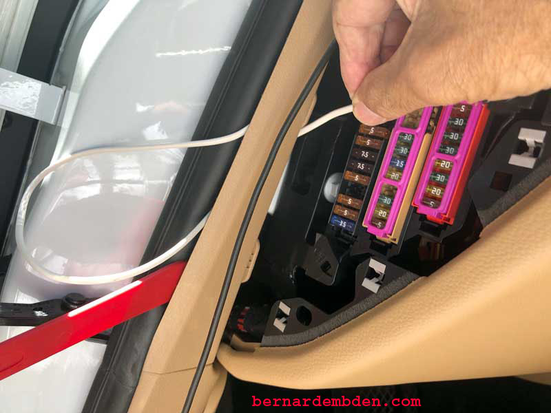
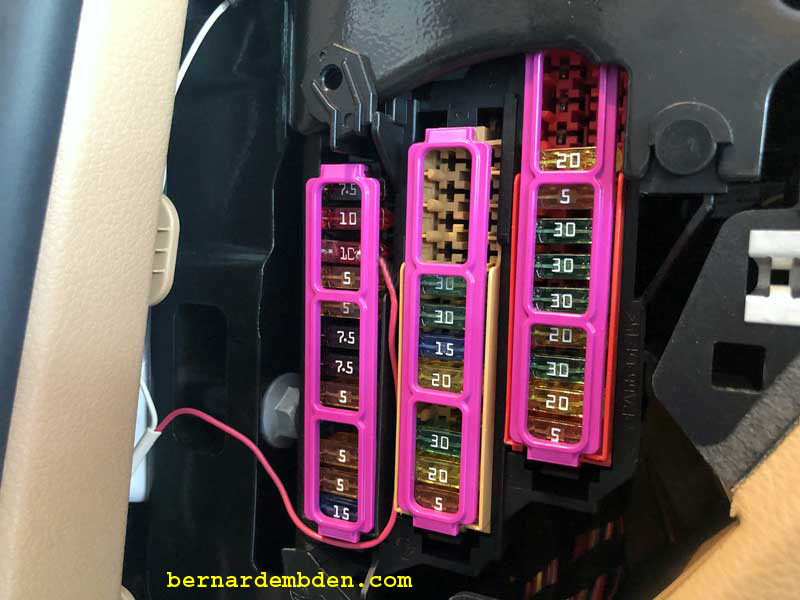
My owner s manual, along with online information, identified the Home Link fuse as a 5 AMP fuse located at the number 3 position in row "A" of the driver s side fuse panel. (photograph below) However the actual number 3 fuse in the driver’s side column A is 10 AMPS.
Pulling the number three 10 AMP fuse cut power to the Home Link system and a temporary connection to my detector power cable confirmed that was indeed the correct fuse. (photograph below)
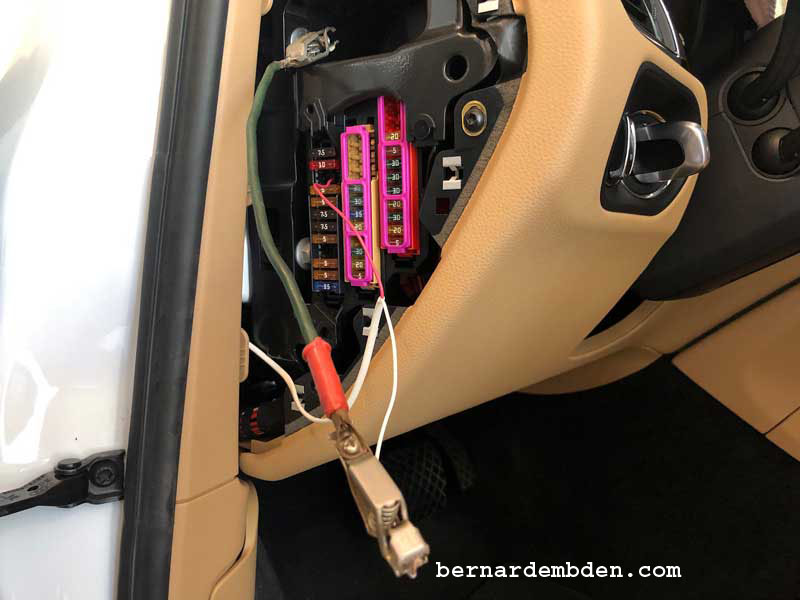
I decided to use a fuse tap. Available from the usual automotive suspects, it’s designed to provide two fusible circuits powered by one factory fuse location. (White arrow photographs below).
I used the top stud as my ground contact by placing the ground wire between two washers (red arrow). After installing two 10 AMP fuses in the fuse tap, (white arrow) it was installed in position number three in the fuse panel.

Test power to the detector. Attach Blend Mount adapter and install on mirror stem.
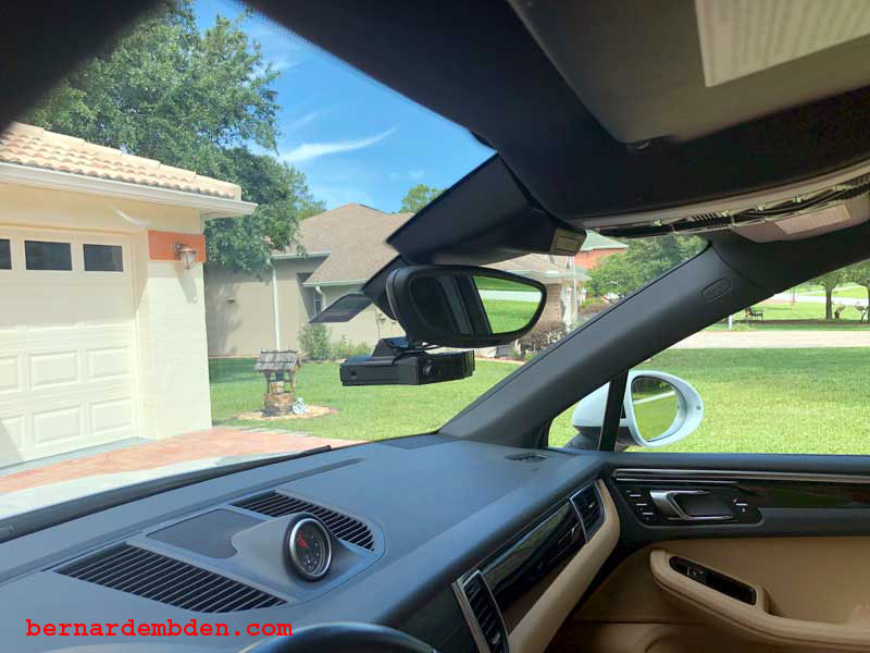
For those discerning Macan owners who might notice that my SunPass sticker might block the rain sensor, (I know, I know). I put it there because it looks better in the center as opposed to Porsche s recommendation to place it at the side of the sensor array.And if I have to, I am perfectly capable of turning on my own wipers.
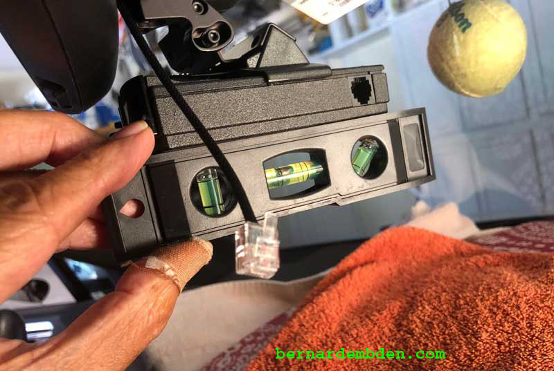
Attach detector to Blend Mount adapter. I use a level to set the initial horizontal plane.
If done correctly, the Mirror Tap power wire routing cable should look like the photograph below.
Attach the new clips (or carefully re-bending the old clips based on the prior photographs) to the overhead console and reinstall being careful with the console trim.
The following photographs show the completed project.
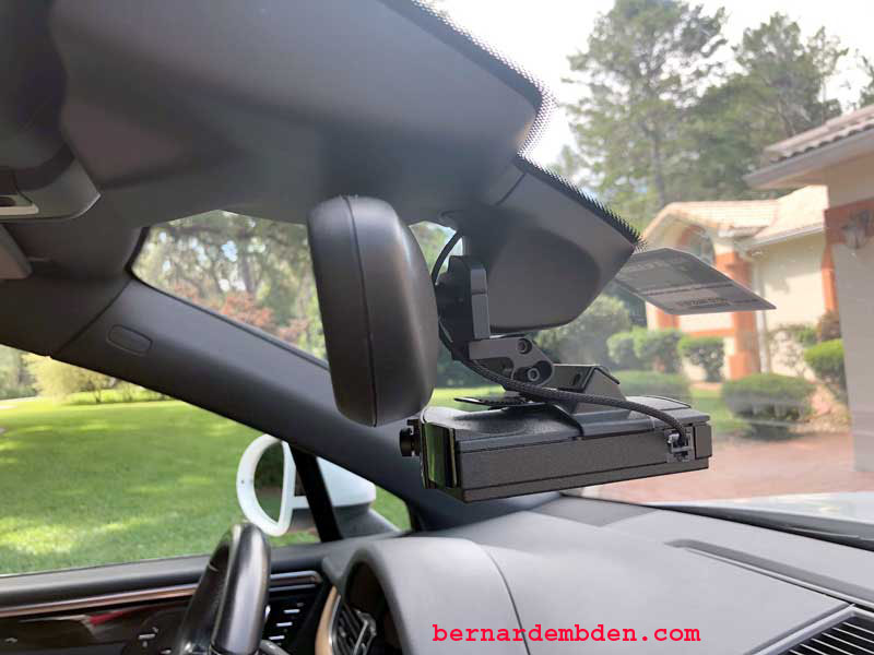
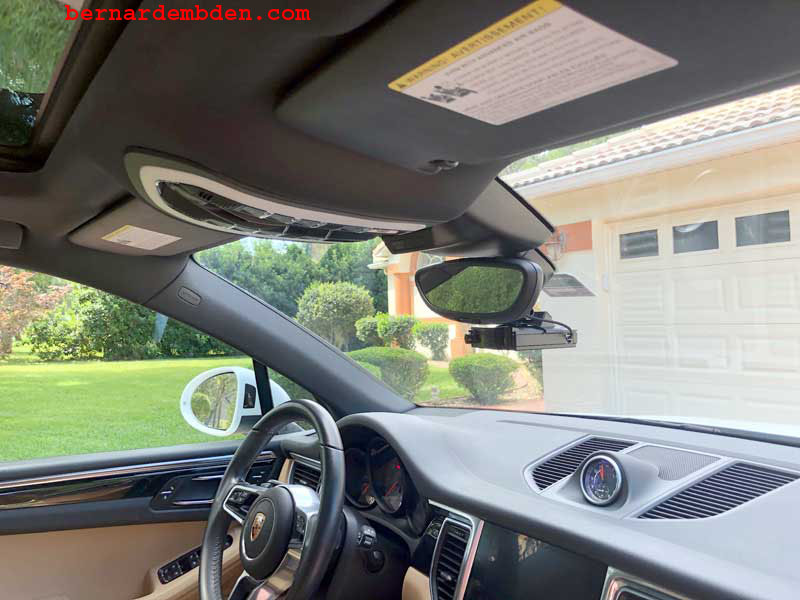
This is not an easy project, but it’s only scary if you break something.
