
My air conditioner refuses to turn off. When the A/C control is turned to the off position, the blower fans would actually switch to the high position, as if it had a mind of its own. Even though I live in Florida, on the rare occasion that I turn the AC off, I would like the thing to actually turn OFF.
The problem appears to be the Air Conditioning Control switch, located to the right of the radio. A more accurate description would be the HVAC mode selector switch, since it controls not only air conditioning, but heating functionc as well. Diagnosing the switch seems simple enough, however nothing is simple with this car. The challenge is actually getting to the damm thing.
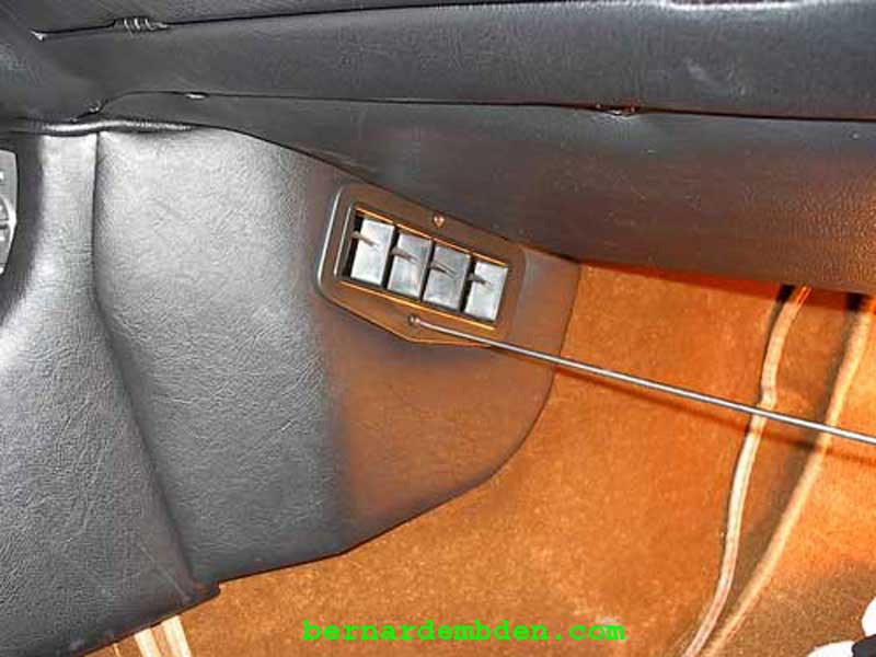
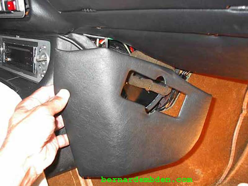
The project starts by removing the right and left foot-well vent fascias and side panels.
Remove the ski-slope.
Remove the A/C control knobs, radio and radio support bracket.
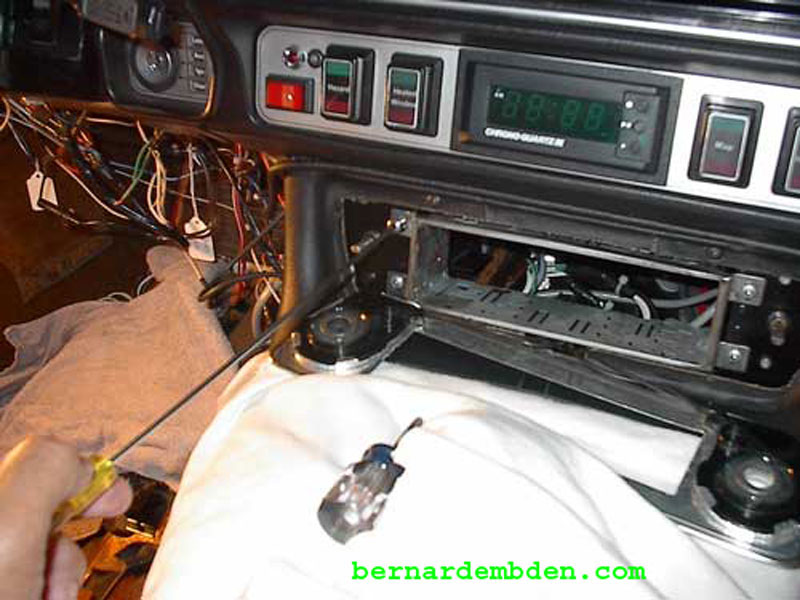
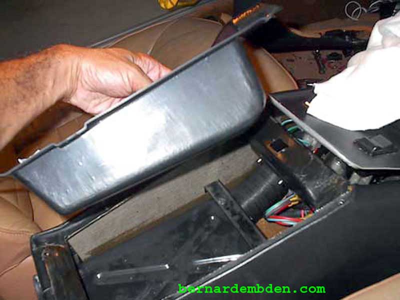
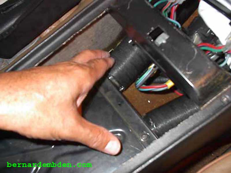
Remove console armrest cover and console bin. This will give you access to the two tubes that are part of the HVCA system that feeds heating and air-conditioning to the rear passenger compartment. These tubes must slide off when the console moved back.
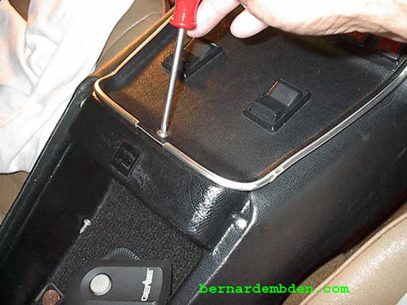
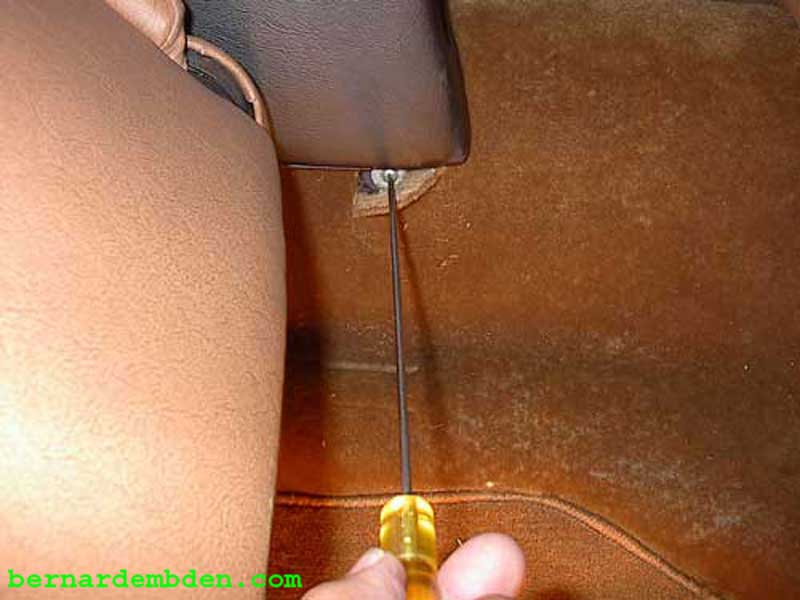
Remove rear console mounting screws. The two screws are accessed from each side of the rear passenger compartment under a slit in the carpet.
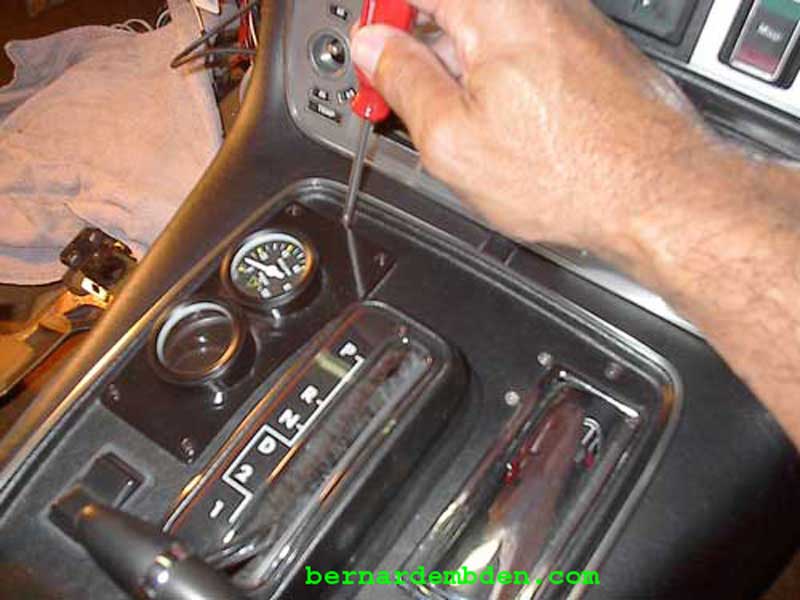
Remove the two upper console screws that attach the front of the console to the dashboard support.
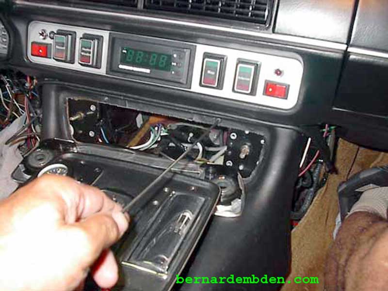
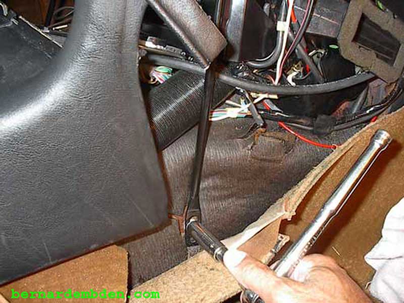
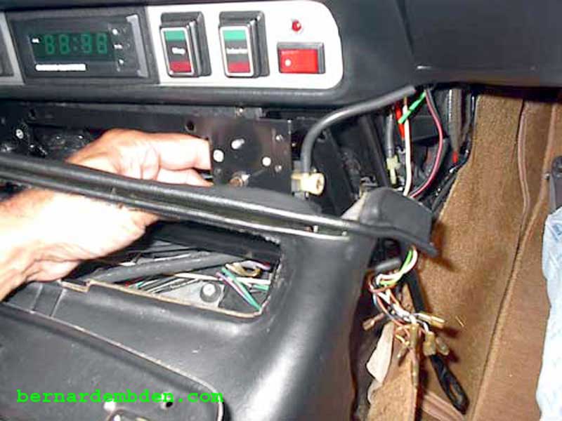
Hold the ski slope up and slide the console to the rear. This will allow you to remove the bottom bolt from both dashboard side support struts. Swing the struts slightly outward.
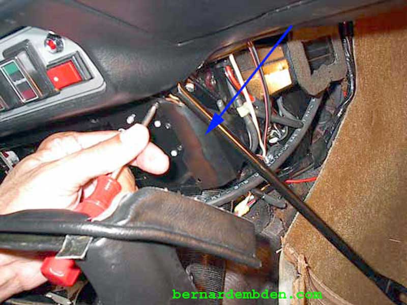
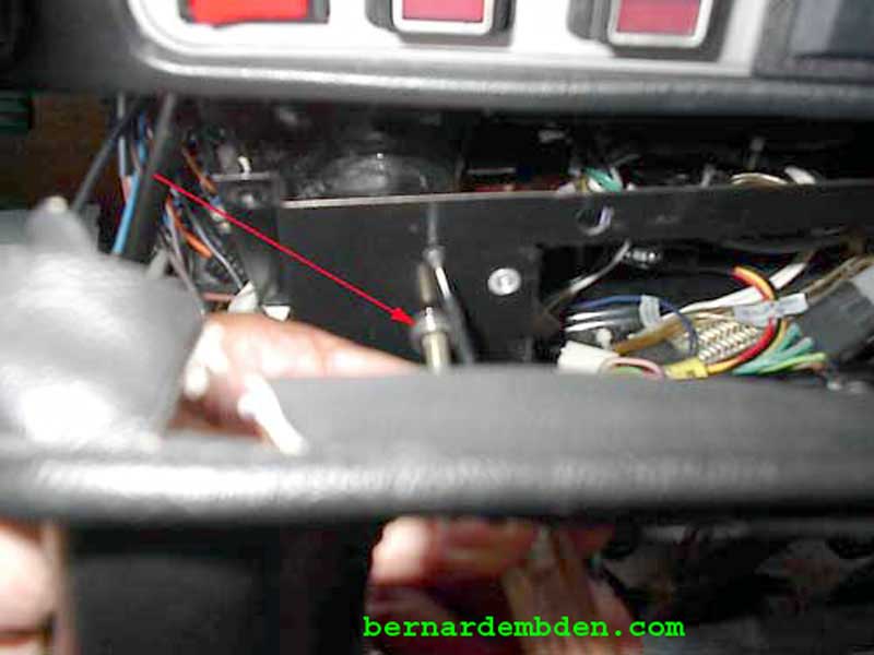
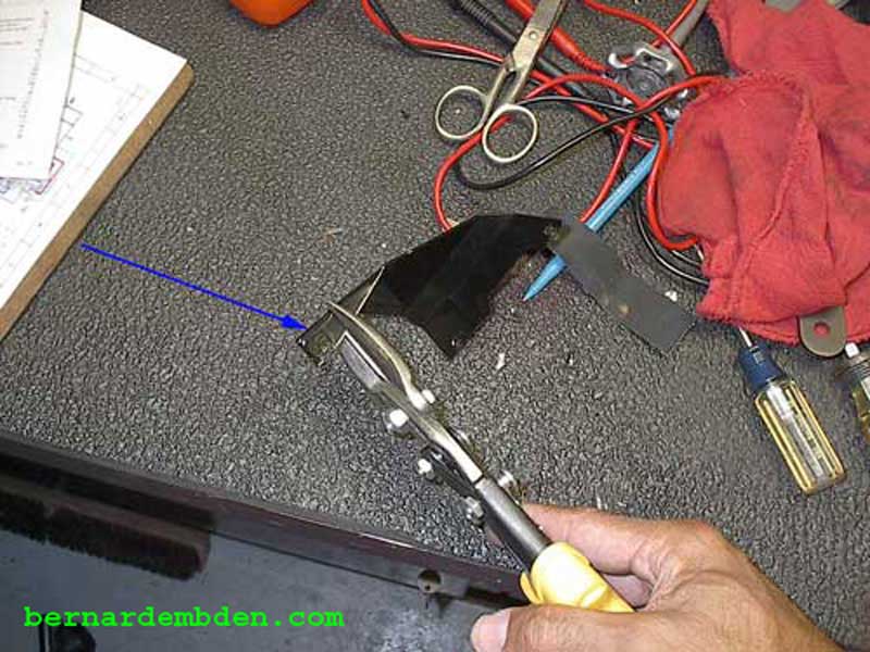
The A/C mode selector switch connecters are covered and protected with a metal bracket. (blue arrow) Remove bracket by removing two Phillips screws and the lower A/C bracket stud screw.
Remove the four screws (two each side) holding the A/C control bracket to the lower dashboard support.
Remove the two Phillips screws that secure the HVAC temperature control switch located on the left side of the radio opening and remove the switch.
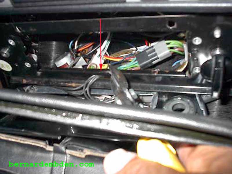
The fiber optic cables than illuminate the two HVAC control knobs are routed through an opening in the bottom of HVAC bracket. I don't recommend disconnecting the fiber optic lines at the control assemblies. The plastic is brittle and might crack. Instead, using tin snips, cut an opening in the bracket to release the fiber optic cables. (red arrow)
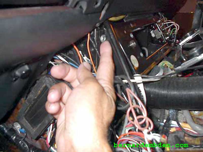
The entire radio/HVAC fascia with the fiber optic lines still attached can be pushed through the HVAC mounting bracket opening, allowing the bracket to be removed from its mounting studs.
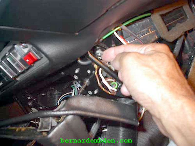
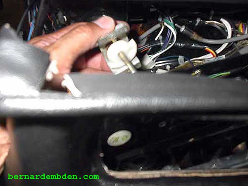
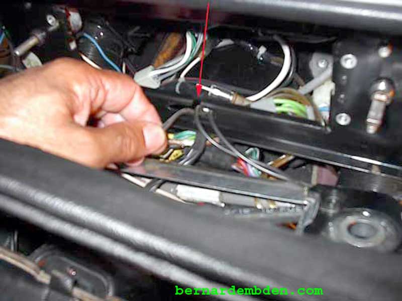
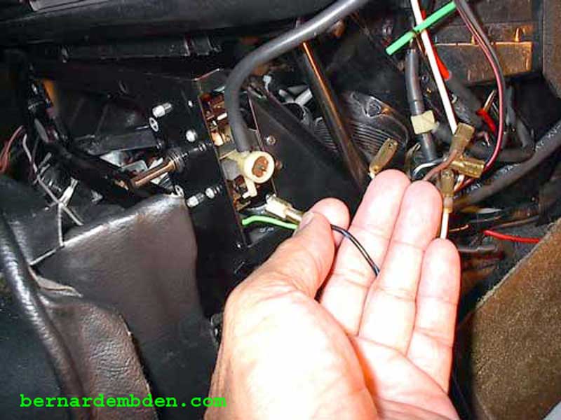
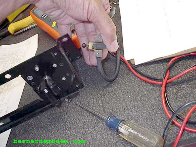
The wires and vacuum switch connecter for the HVAC mode selector switch is now visible. Remove the two vacuum switch hoses.
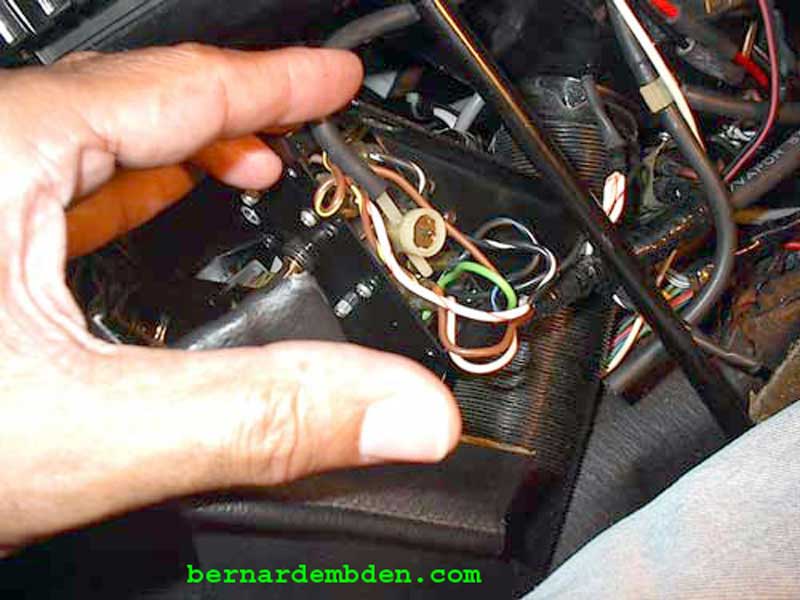
Identify and tag (repeat, Identify and Tag) each wire color and its micro-switch location before removing them from the four micro-switches that comprises the switch assembly.
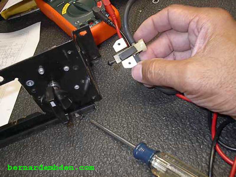
Remove bracket (with HVAC mode selector switch) onto work bench and remove vacuum switch held in place by two Phillips screws.
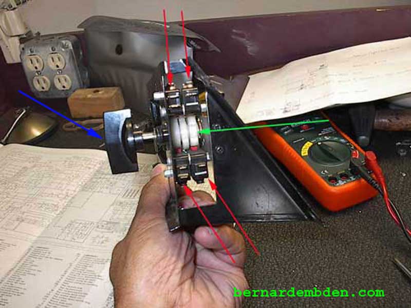
Photographed below are the four micro-switches (red arrows) that makes up the HVAC mode selector switch. They are actuated by the cam lobes (green arrow) as the assembly is rotated via the control switch knob. (blue arrow).
Photographed below is a wiring diagram of the HVAC system. Note that I colored the wires to make it easier to read. The colors do not correspond to Jaguars wiring system.
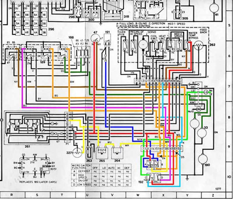
The wiring diagram main modules are identified below:
(33) Blower motors
(47) AC Water temperature sensor.
(188) AC Blower resisters.
(189) AC Blower relay.
(190) AC Compressor clutch.
(191) AC Thermostat.
(192) HVAC mode selector switch.
(261) AC Amplifier.
(262) AC Servo assembly.
(263) AC Vacuum valve.
(264) AC In car sensor.
(265) AC Ambient sensor.
(327) AC Temperature selector.
In addition, number 192 (HVAC mode selector switch) is comprised of four micro-switches, A/B/C/D that are further detailed as "Micro Switch Functions" at the bottom of the wiring diagram.
Using the wiring diagram's Micro Switch Functions and a test meter identify the correct function of each micro switch as the cam lobes are rotated through the switch's range of motion. Once the defective switch is identified, removed and replaced It.
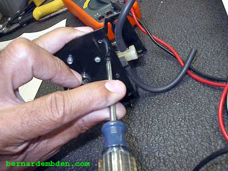
Reinstall HVAC bracket. Install temperature control switch. Before installing HVAC mode selector switch wire cover, modify by removing the bottom stud support. (Photographed below) This will allow you to install the cover without fitting it under the bottom stud, which is a real PIA.
Move console forward into correct position. Make sure rear HVAC tubes are connected before final assembly.
Install ski slope, console bin, radio etc.
Project complete.
