
It's hard to find fault with the driving position of my 1978 Jaguar XJ-S, however, while driving my left foot tends to rest at a somewhat uncomfortable position on the floor.
This car needs a Dead Pedal.
Essentially a support for the drivers left foot. This might not have been a priority in 1978, when ergonomics was nothing more than a trivia question. It was now a propriety.
Some Jaguar owners have resorted to putting a piece of wood underneath the carpet to function as a surrogate "Dead Pedal". You know that would not be acceptable to me.
The XJ-S foot well is narrow and deep. Finding the right size dead pedal would be critical. In addition I was determined not to drill holes in the floor pan or side panels.
I looked at "Dead pedals" from local auto stores. Most were aluminum and did not provide the look I wanted. I finally sourced a generic "brake pedal cover" from JC Whitney, a mail order automotive store in the US. This cover is actually a rubber pad over a metal plate and measures 6 x 2.5 inches. This was the size I wanted.
A trip to Home Depot provided the additional raw materials.
1) Single outlet surface mount electrical connector box designed for outside installation. Size 4.5 x 2 x 3 inches.
2) 24 inches of 2 inch wide metal stock.
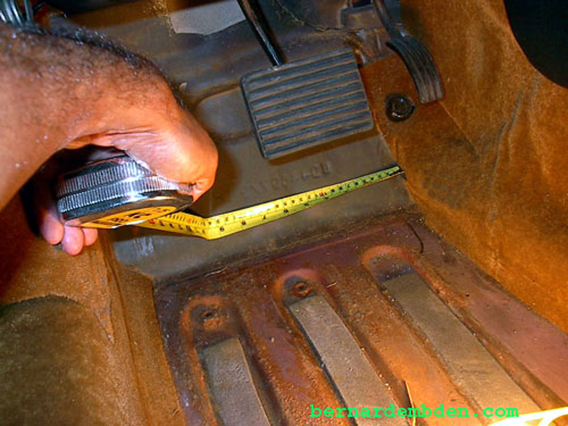
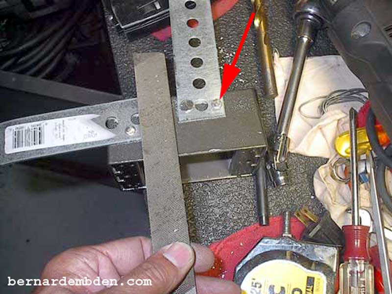
I started the project by measuring the width of the foot well just below the brake pedal and cutting the 2 inch wide metal stock to length. (photograph below)
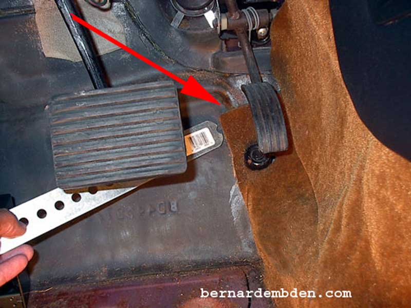
The metal stock will fit in a slight indentation in the floor pan (red arrow photograph below). I rounded off the end of the metal strap to conform to its intended location.
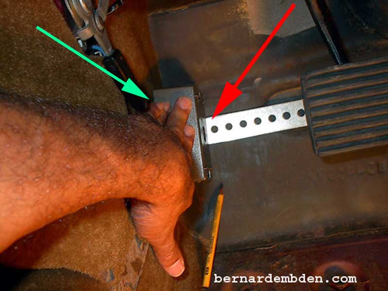
As seen in the photograph below, place the metal strap to butt up tight against its intended location. Place the electrical outlet box sideways and mark the location of the strap against the electrical box. (red arrow). Note the orientation of the box. It's placed sideways because it gives me the height and width that I wanted. In addition, the opening should face towards the left side, hidden by the side panel. (green arrow).
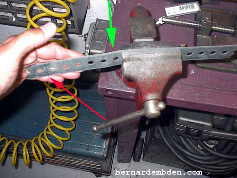
Cut the metal strap approx. 1 inch beyond the mark. (red arrow photograph below). This is necessary for mounting. Bend the strap in a slight "S" shape (green arrow) to allow it to follow the indentation of the foot well.
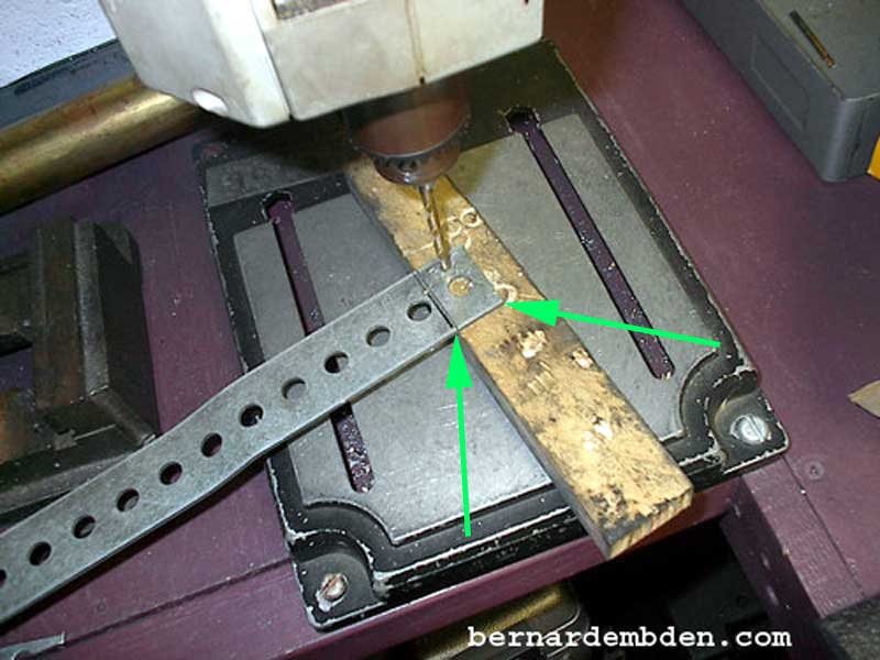
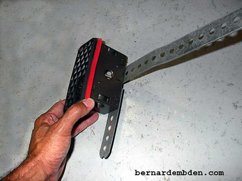
Drill two holes in the metal strap equidistant between the mark on the strap and the end of the strap. (green arrows photograph below). Position the electrical box and the metal strap in its final location in the foot well. Holding the box and strap in its intended location, remove from foot well, invert and mark the location of the holes drilled in the above photograph, to the electrical box. Drill the two marked holes (to accept rivets) in the electrical outlet box. Note the orientation of the box. When installed the strap must be on the "Bottom" of the installed position of the box.
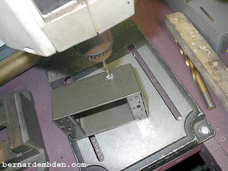
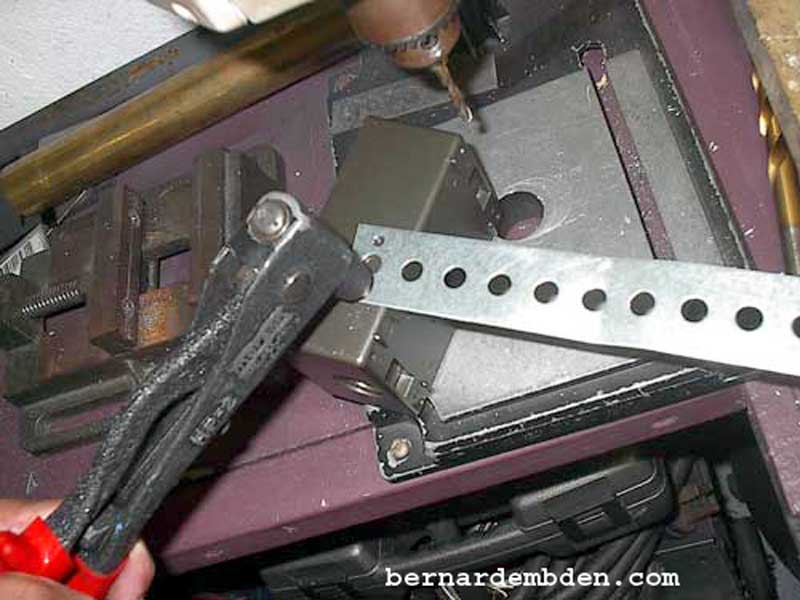
In the photograph below, rivet the strap to the box in two locations (marked and drilled in the above photographs) to prevent the strap from rotating.
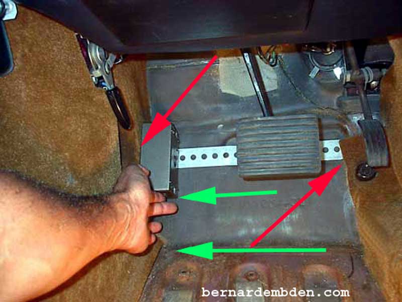
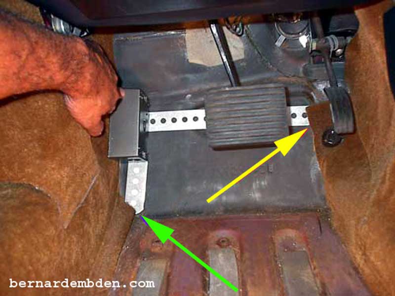
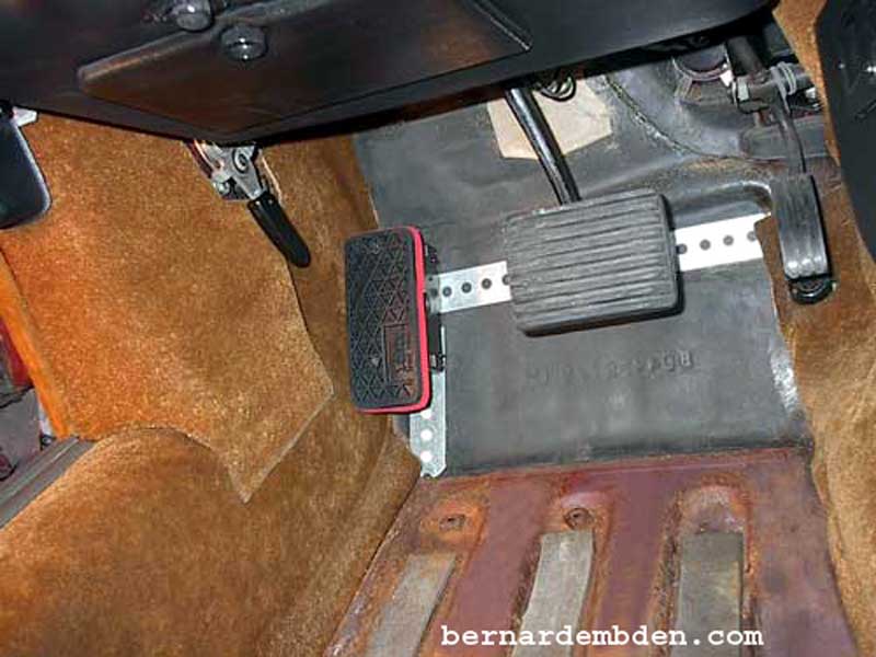
Test fit the installed strap and box. (photograph below) The metal strap should fit snugly in the indentation underneath the accelerator pedal and the box should fit tightly against the left interior panel. (red arrows). Measure the distance between the bottom of the box and the bottom of the floor pan. (green arrows). Add one inch for mounting and cut another piece of metal strap to length.
Final test fit reveals the mounting methodology. The box is held in place by two supporting straps, which locates it vertically and horizontally (yellow and green arrows).
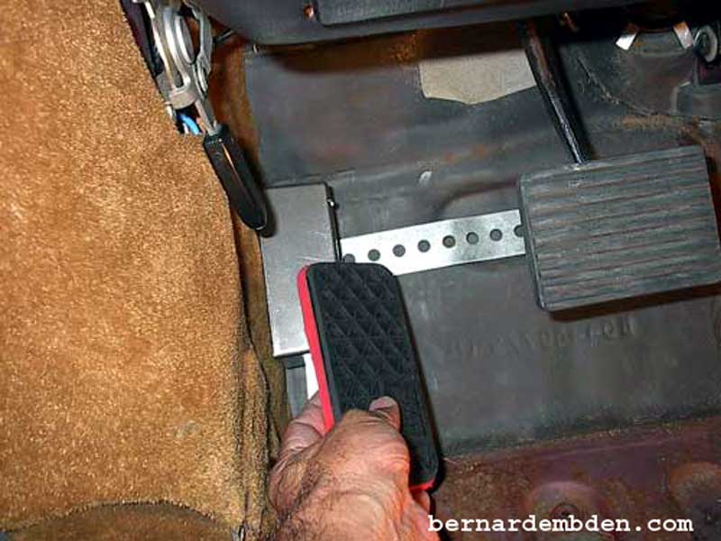
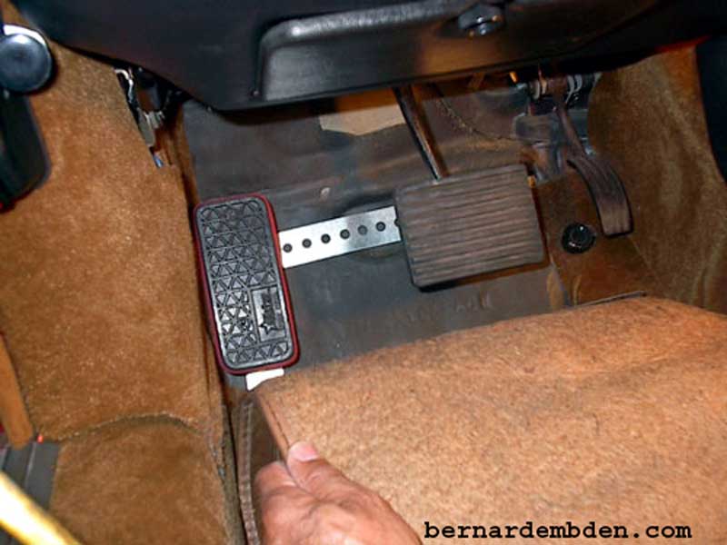
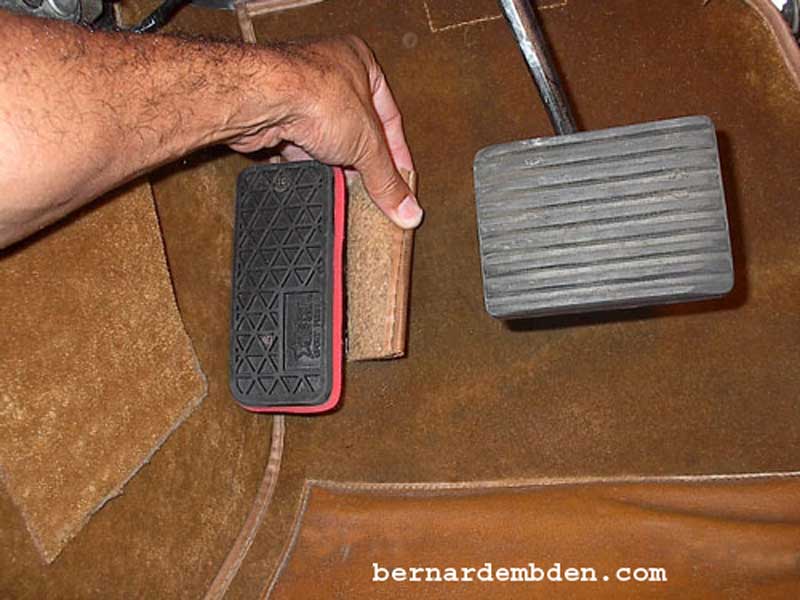
Test fit the "Dead pedal cover" onto the box. It should be snug against the left panel and somewhat centered horizontally. Mark location underneath the cover.
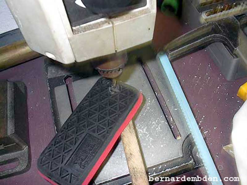
Two mounting holes are all that's necessary to mount the dead pedal pad onto the box. Mark locations and install. I used black screws to blend in with the cover. The electrical box was then painted black.
Pictured below is the completed dead pedal assembly.
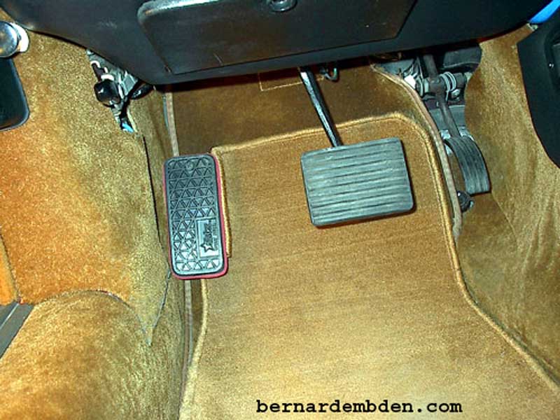
Final test fit with cover installed.
Install the original carpet padding.
I cut two slots (green arrows photographs below) in the carpet to allow it to fold around the dead pedal box. This is the reason the box was installed with the opening against the side panel. By installing the bottom of the box towards the brake pedal the cut carpet is supported, providing for a cleaner more finished look.
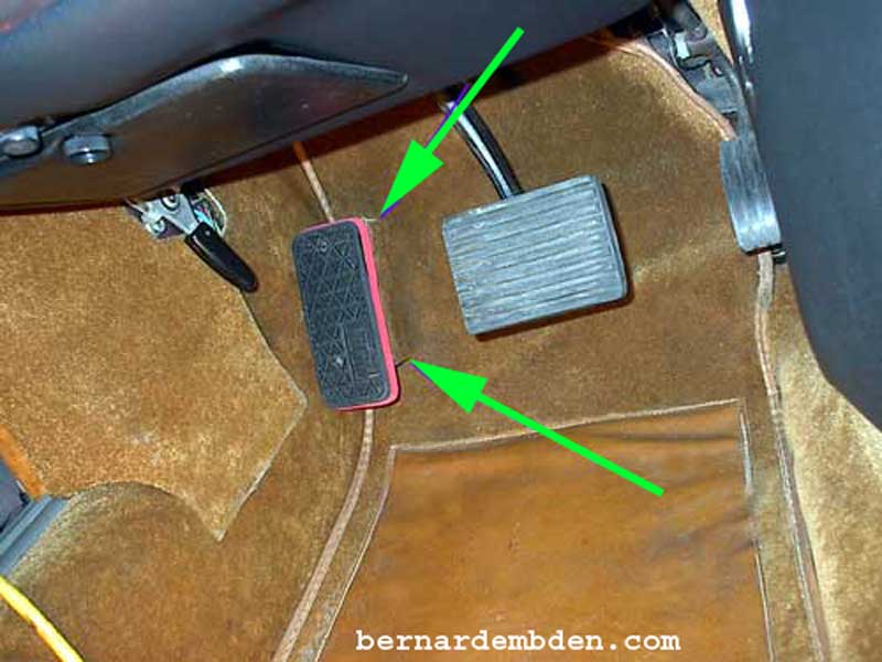
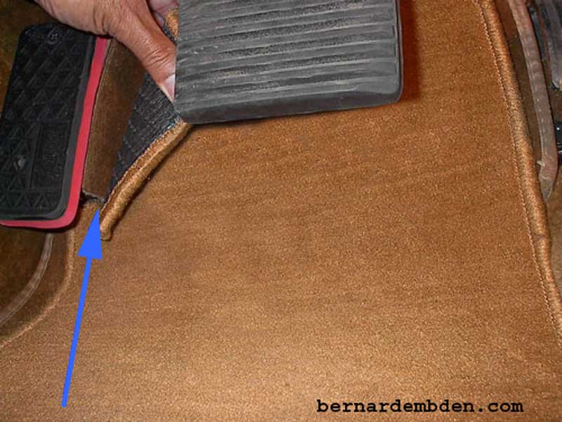
The carpet only needed one small cut. (blue arrow) The rest folded neatly against the side of the box.
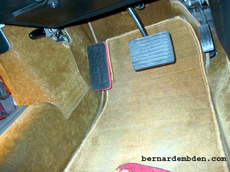
Dead Pedal Project Complete. When finished this should look as if it belongs there.
This is a project that I should have done years ago. The difference in driving comfort is immeasurable.
