
The symptoms are:
1) The whine usually starts after the differential oil has warmed up.
2) The pitch changes or disappears with throttle variation.
Pinion pre-load is lost gradually over the life of the differential as the bearings and or race wears with use. This wear can cause enough pre-load to be lost that the pinion will actually move when torque is applied or removed to the pinion via the driveshaft under engine acceleration or deceleration.
This noise is a result of the pinion shaft moving slightly, thus changing its angle to the ring gear, as on/off engine torque is applied to the differential. In most cases this condition is more of a nuisance than a sign of impending disaster. Further complicating matters, the fix is often worse than the problem. A complete teardown of the differential was necessary to get to, and replace the pinion crush sleeve which controlled the pinion pre-load.
This is exactly the symptom my car was exhibiting, a imperceptibly movement of the pinion under torque variation that produced a slight differential whine.
I was convinced that there was a simpler solution to this problem.
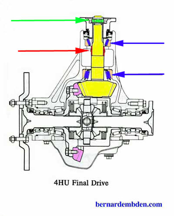
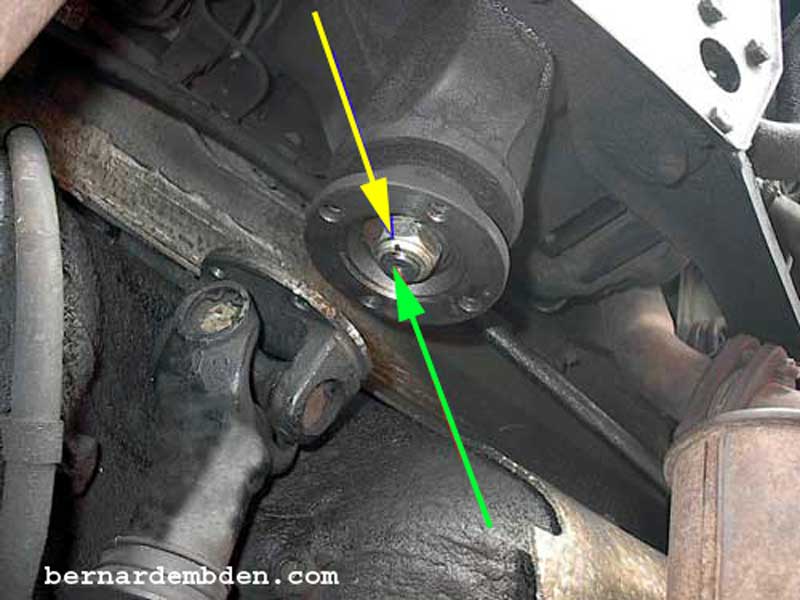
The drawing below shows the Jaguar's differential. Identified are the following:
Pinion-complete(yellow)
Pinion nut(green arrow)
Crush sleeve (red arrow)
Bearing race (orange)
Bearings (blue arrows)
Ring gear (purple)
The pinion (yellow) rotates via the driveshaft and turns the ring gear (purple) which is bolted to the differential carrier. The drive axels connect to the carrier via splined openings.
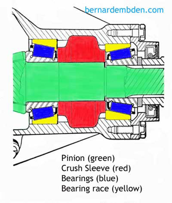
Illustrated below is a detailed drawing of the pinion assembly of a typical differential:
Pinion pre-load is the force (pressure) between the pinion bearings (blue) and the pinion bearing's race (yellow). As the pinion nut is tightened it forces the yoke against a "crush sleeve" (red) that is designed to "control" collapse under force. Not enough force from the pinion nut and the crush sleeve holds the pinion bearings too far away from the pinion race resulting in not enough pinion pre-load. Too much force will collapse the crush sleeve and apply too much pressure to the pinion bearings (blue) against the pinion race (yellow), resulting in too much pinion pre-load.
Too much pinion pre-load cannot be undone. The crush sleeve, once compressed, stays compressed. Backing off the Pinion nut once the sleeve has been compressed does not result in less pinion pre-load, it results in NO Pinion pre-load.
Of the two conditions, not having enough Pinion pre-load is far preferable. A Pinion with too much pre-load will overheat and destroy the pinion bearings requiring a complete differential teardown and rebuild.
My objective was not to reset the Pinion pre-load, but to increase the Pinion pre-load incrementally until Pinion movement was eliminated. To accomplish this I needed some way to measure Pinion "drag" between the ring gear backlash. The proper tool is an Inch pound torque wrench; however I had no intention of purchasing one for this project. The challenge was to fabricate an acceptable substitute.
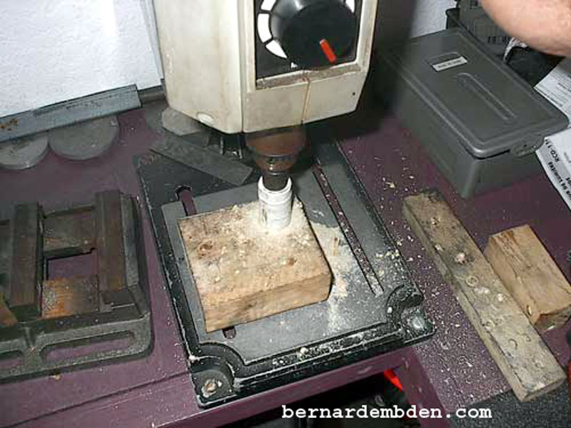
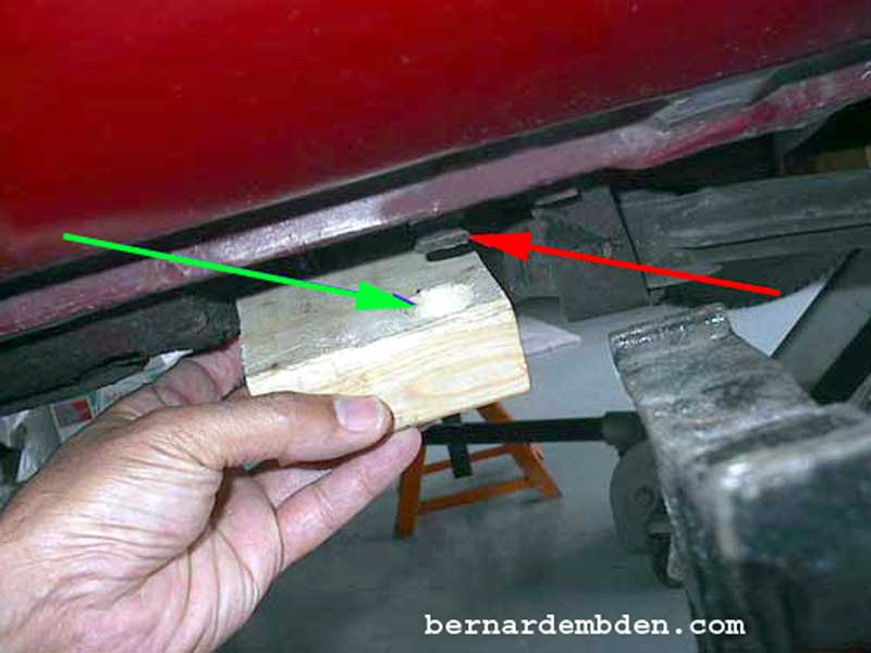
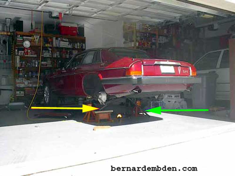
For this task I needed the car to be on jack stands a minimum of 20 inches off the ground. Note that safety is an issue. Supporting the front of the car with jack stands is not a problem, however the rear jacking points are designed to accept the factory jack. To properly support jack stands I recommend a modified "pad" between the jack stand and the body jacking point. Start with a section of 2x4 lumber and drill a 1 1/2 inch hole in one corner. (photographs below)
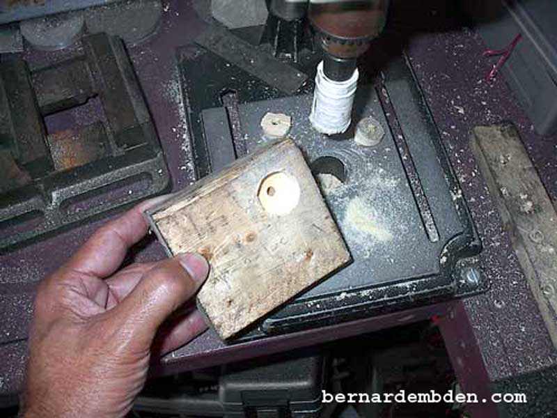
In the photographs below, the recess in the 2x4 (green arrow) accepts the jacking point (red arrow) on the rear jacking point of the car.
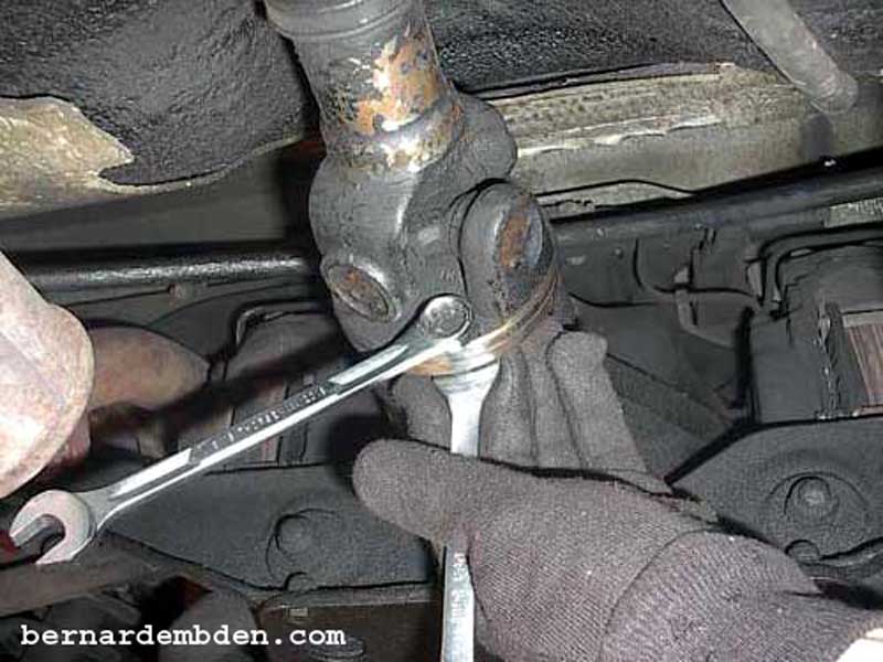
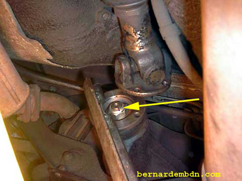
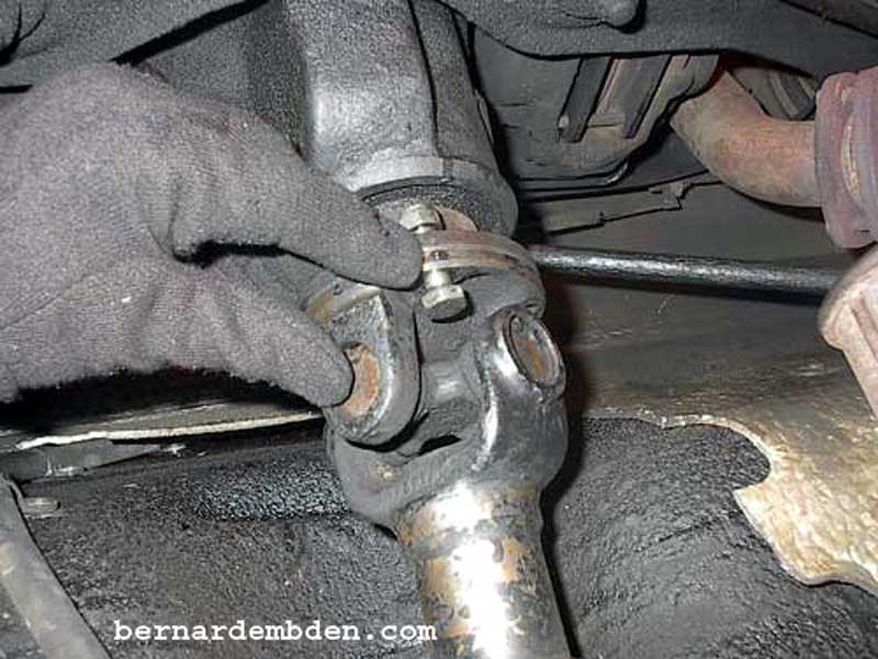
You will need two 9/16 wrenches to remove the driveshaft coupling bolts.
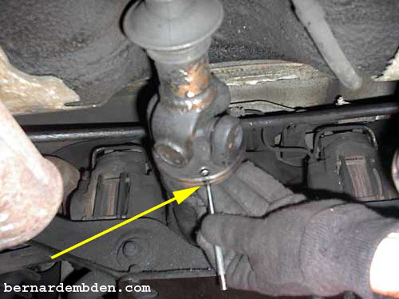
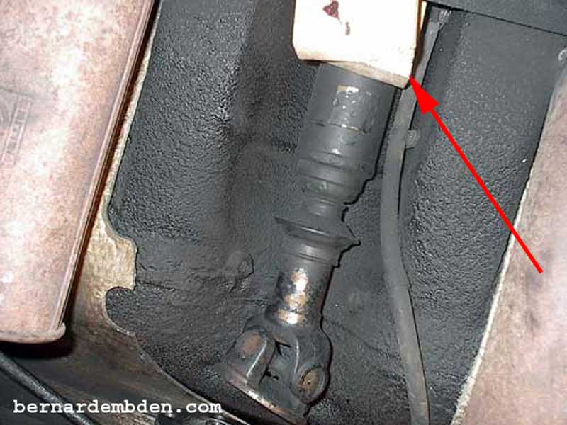
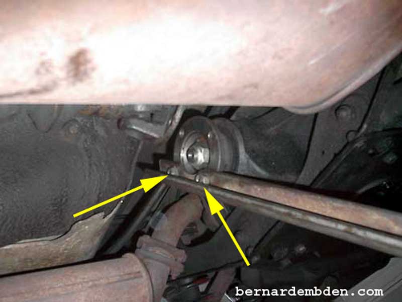
I recommend marking the position of the driveshaft (yellow arrow photograph below) to ensure reassembling in the original position.
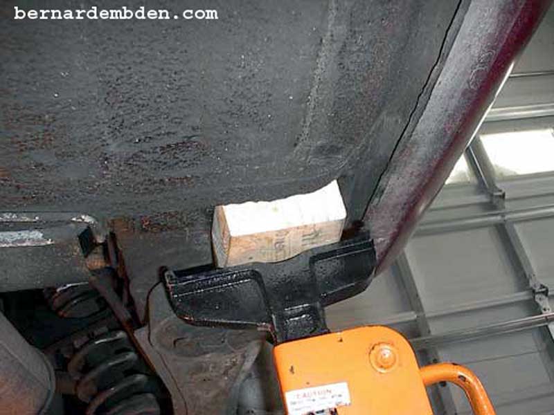
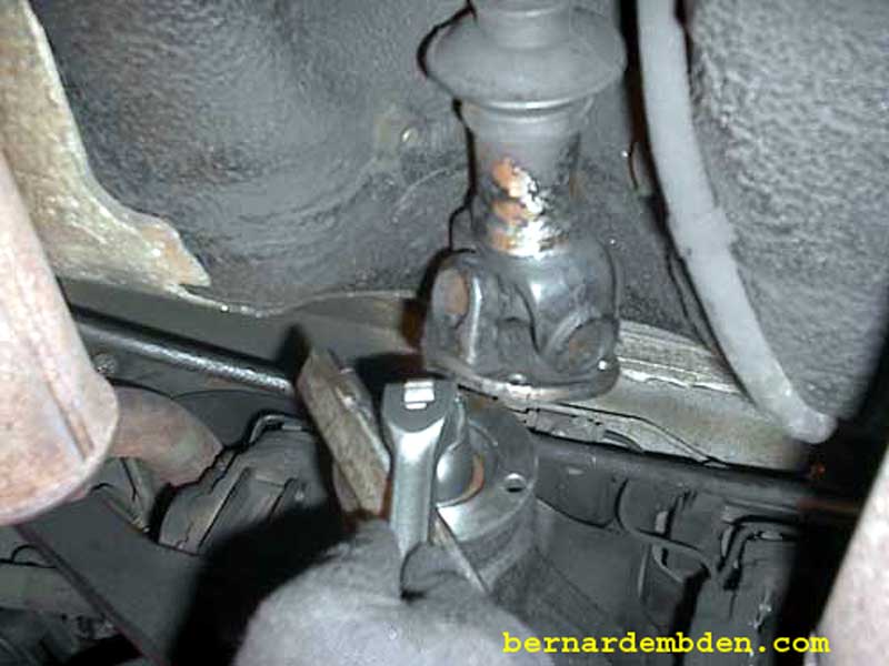
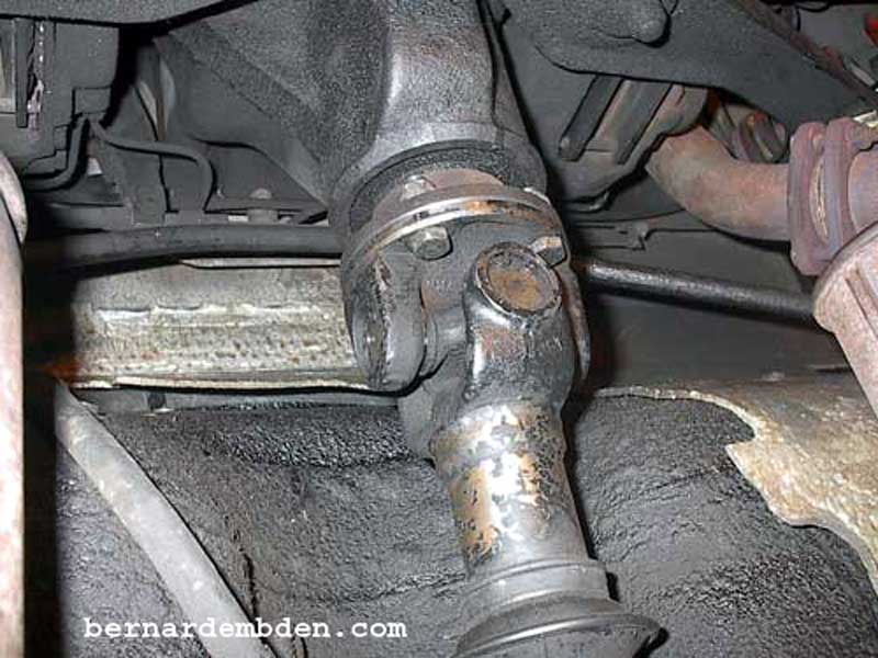
Having no intentions of actually removing the driveshaft, I shimmed it up with two pieces of 2x4's to gain access the differential pinion nut. (red arrow photographs below)

Now is the time to check the Pinion assembly. Rotate the yoke. It should turn freely between the backlash. There should be no binding, obstruction or noise as the pinion rotates. If any of these symptoms are present the differential needs to be rebuilt. Reattach the driveshaft and consume some alcohol.
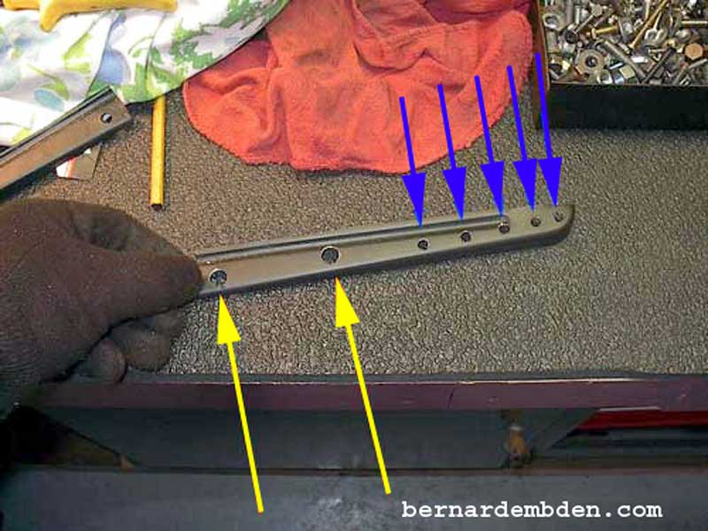
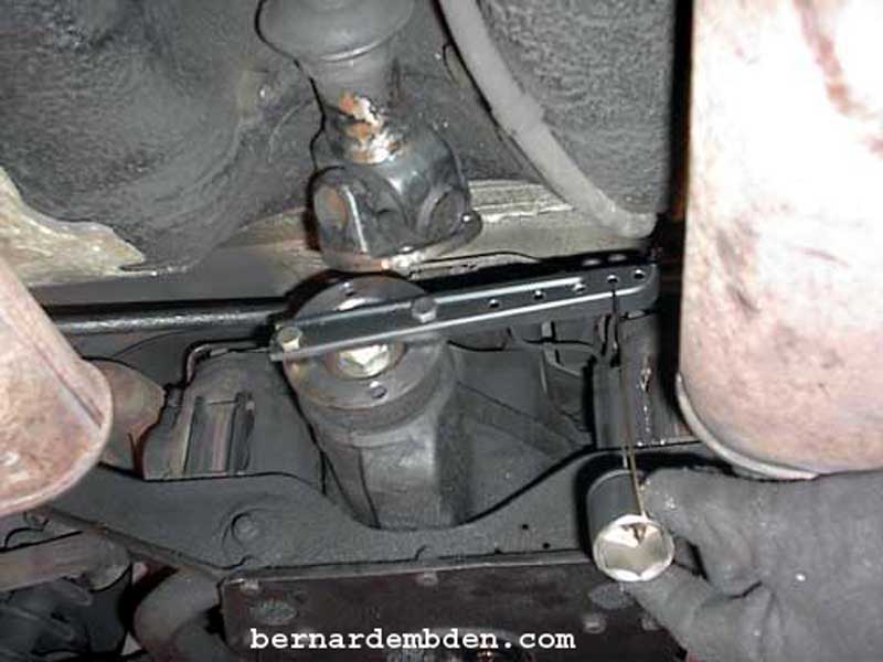
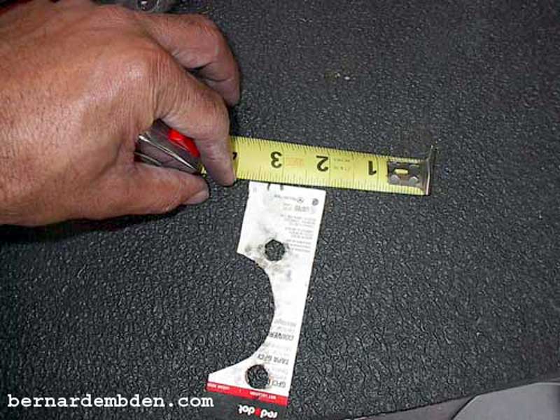
My differential pinion did not exhibit any of the above systems, so the project continues. In the photograph below, I fabricated a "scale" by using a piece of stock metal 9 inches in length. The two holes (yellow arrows) are 3 1/8 inches apart and will attach to the pinion yoke. The other 5 holes (blue arrows) are 1/2 inch apart and will provide some weight adjustability.
The "scale" is bolted to the pinion yoke's flange and aligned horizontally.
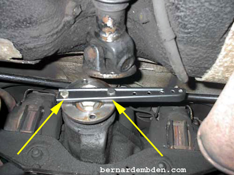
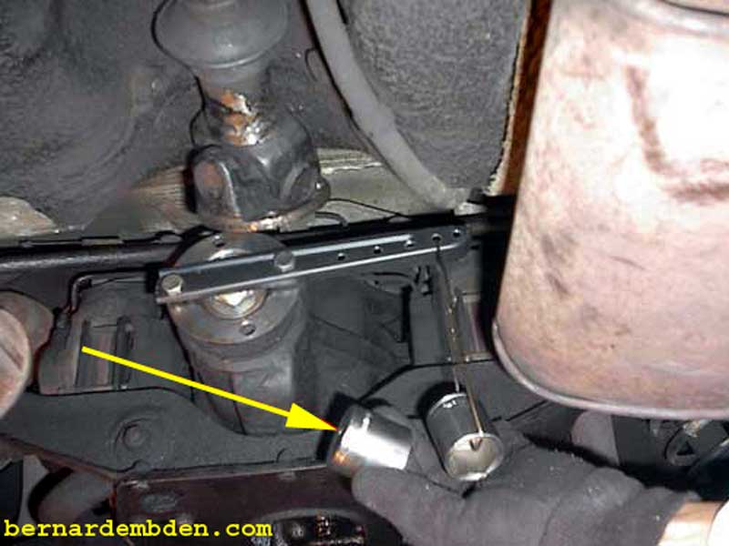
In the photograph below, I used a section of a coat hanger to hang weights off the end of the "scale". After some experimentation a 1 1/8 inch 1/2 inch drive short socket (green arrow) hung off the 4th hole (red arrow) was just able to move the yoke between the ring gear backlash. Take your time on this. The backlash is the distance the pinion moves between the teeth of the ring gear. It's not much, but it's clearly identifiable.
I now had established the current pinion drag baseline I needed.

In order to move the pinion nut a considerable amount of force is needed. Securing the pinion yoke while this force is applied requires a special tool. You could buy one, or you could make one. You know I am not about to purchase this tool. I started with an old bumper jack. You can source these at any junk yard. The main shaft is "V" shaped with notches that the jack assembly ratchets against. It's extremely strong, designed to support a medium sized car. I removed the shaft and drilled a hole 2 inches from one end. With this material, it's easier to start with a small drill bit and work your way up to the proper size.
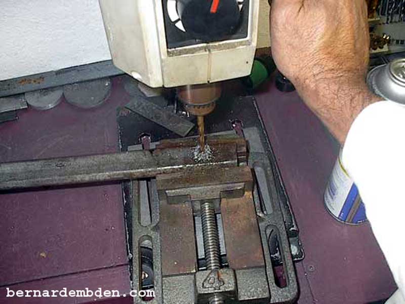
Using a template that I made of the pinion flange I transferred the position of the second hole and the clearance necessary to access the pinion nut. (photograph below)
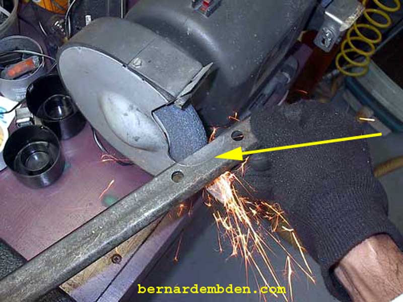
The jack shaft is extremely tough, however some time on the grinding wheel removes the necessary material. (yellow arrow photograph below)
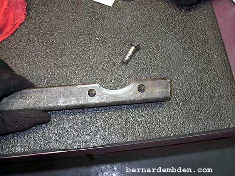
Pinion yoke holding tool completed.
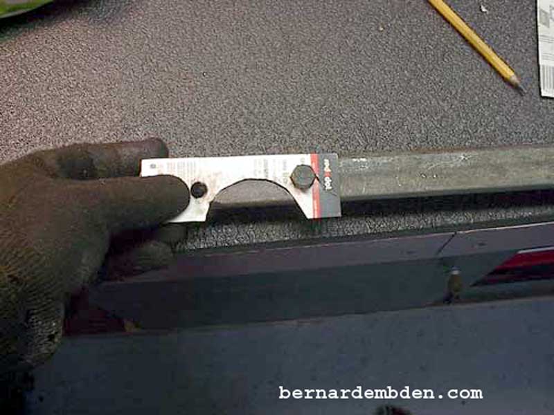
Attach the holding tool to the pinion yoke using two bolts and nuts. (yellow arrows photograph below).
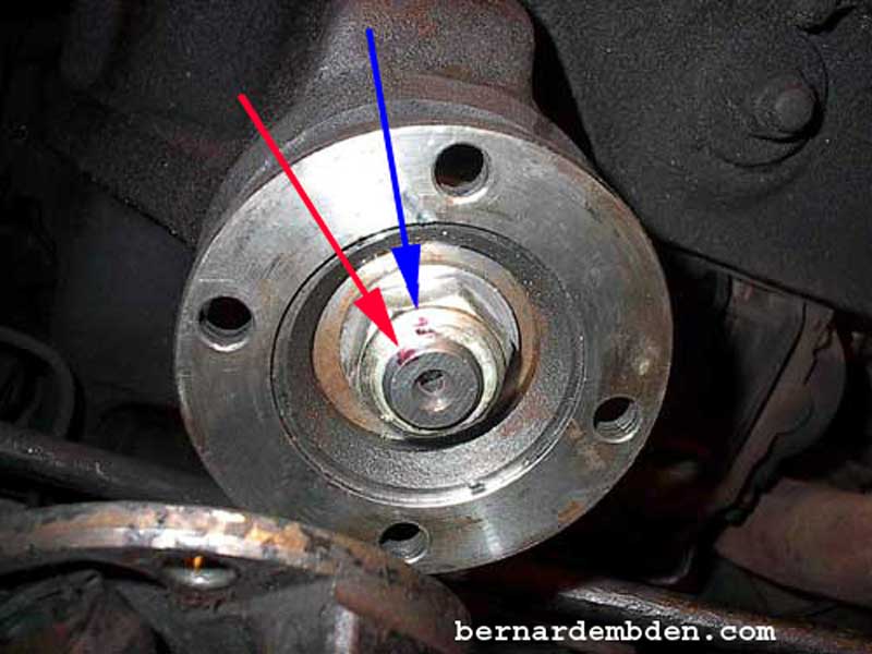
A reference point is critical to this project. The pinion nut and pinion must be marked. I recommend using paint with a small brush making sure to mark both pinion and nut clearly. (yellow arrow photograph below).
You will need a 1 1/8 inch 12 point 1/2 inch drive socket attached to a breaker bar to move this bad boy.
Photograph below. This is the reason you need the car on 20 inch jack stands. The pinion yoke holding tool (yellow arrow) is supported while a pipe is placed over the breaker bar (green arrow) to increase leverage. Stop immediately the nut moves. This process must be done in 1/8 inch incremental movements of the pinion nut.
Photographed below is the movement of the pinion nut (yellow arrow) relative to the pinion. (green arrow) Based on the original markings, the movement is approximately 1/8 inch (3.175mm).
Remove socket and yoke holding tool. Re-attach the scale. Make sure you use the same bolts and nuts in the same locations. I attached the original weight in the original location. There was a slight drag. The movement was not as free. If I manually started the process the original weight moved the Pinion halfway between the ring gear backlash. I decided to slightly increase the pre-load.
This is crucial. The nut must not be turned more than 1/8 inch (3.175mm) without checking the pinion drag using the scale. Over tightening the pinion nut resulting in too much Pinion pre-load will not only ruin your day, it will ruin your week!
I reinstalled the holding tool and socket to the pinion nut. I leaned on the breaker bar to achieve another small incremental movement of the pinion nut. The photograph below shows the pinion nut has now moved approximately 1/4 inch. (blue and red arrows photograph below).
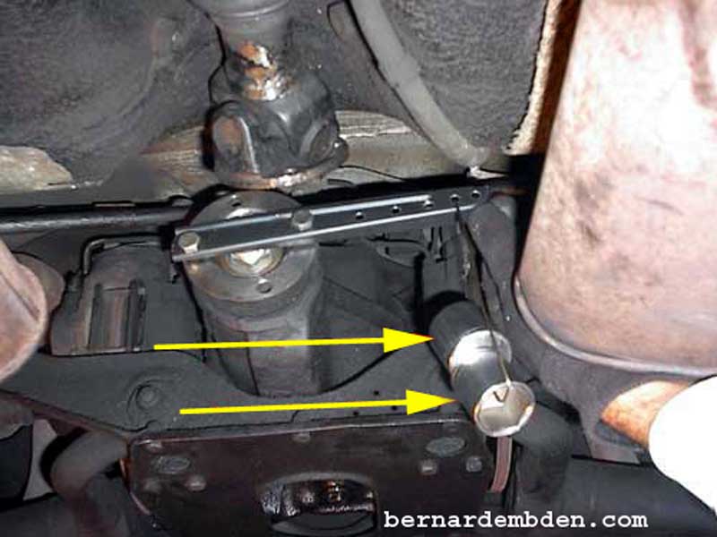
I removed the socket and yoke holding tool and reinstalled the scale. The original weight would not move the pinion yoke. It required an additional 1 1/4 inch 1/2 inch drive short socket (yellow arrows photographs below) attached to the scale to initiate yoke movement. I had achieved the desired result, a slight, measurable increase in the pinion drag between backlash.
The important factor is not that it required another socket attached to the scale to move the pinion. The important factor is that the original weight would no longer move the pinion.
The pinion nut must not be tightened after this point has been achieved.
Transferring the pinion nut movement and measuring it indicated the pinion nut had been moved a full 1/4 inch (6.35mm).
Reassembly driveshaft making sure the original marks is aligned.
Project Complete.
Under test driving conditions the differential whine has been almost completely eliminated.
This is a project where attention to detail is critical, however it's well within the ability of most DYI owners.
