
After driving for some time the engine in my 1978 Jaguar V-12 would exhibit some visible blow-by. Blow-by is produced when some of the combustion mixture that burns in the combustion chamber is forced by the piston rings during the compression stroke. This usually occurs when the piston rings have lost some of their sealing ability due to age. This mixture then becomes saturated with engine oil producing "blow-by". Blow-by is always accompanied with increased pressure in the crankcase, which, if not addressed, can cause engine and crankshaft seals to leak.
The factory solution, consistent with all current manufactures, is to relieve crankcase pressure (and any subsequent blow-by) by providing a pressure relief path back to the intake manifold where it is added to the incoming air/fuel mixture and burnt in the combustion chamber. Once blow-by becomes laden with oil and visible, it is my belief that burning it in the combustion chamber is detrimental to the engine, resulting in deposits on the head surface, pistons and valves.One solution is to vent the crankcase, and associated blow-by, outside the engine. This not only pollutes the environment but also looks unsightly. It's difficult to look cool with puffs of smoke coming from beneath the engine.
My initial solution was to filter the blow-by before it was drawn back into the engine and burnt. I installed a custom filter, however after a few hundred miles the filter became practically useless as it was saturated with oil from the blow-by. I could install an aftermarket catch can, however I like to make things.
A comprehensive solution was called for. The problem was how to handle the oil particles in the blow-by. For this project I decided to fabricate an air/oil separator that would separate most of the oil from the blow-by before it was drawn back into the engine.
The requirements would be that the separator/filter would be reusable, be self-contained and finally, cannot add clutter to the engine compartment.
An additional requirement, modify the Positive Crankcase Ventilation (PCV) system so that it actually works.
A couple of days at Home Depot, local parts store and an order from Coventry West (Jaguar supplier in Atlanta) ensured that I had the necessary parts for this project.
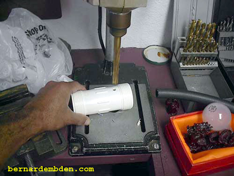
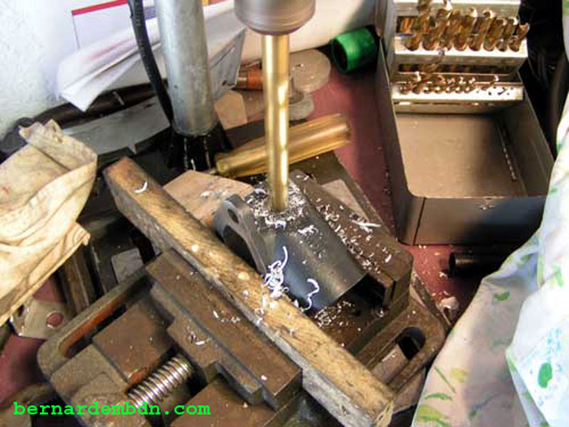
Using a Polyvinyl Chloride (PVC) 2.5 inch repair compression sleeve I drilled a 1/2-inch hole 1 1/2 inches from one end. This would place the air/oil separator entry 2 inches above the bottom of the filter.
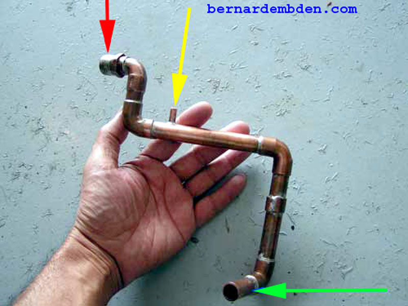
Tap the new hole to accept a 1/2-inch copper pipe threaded fitting. I modified the fitting with a 90-degree elbow. Drill the threaded part of the fitting with a 1/2-inch bit. The 90-degree elbow is then soldered to the front of the fitting as shown in the photograph below. Remove 1/4 inch from the copper elbow (red arrow) to allow it to rotate while screwing the fitting into the PVC housing (green arrow).
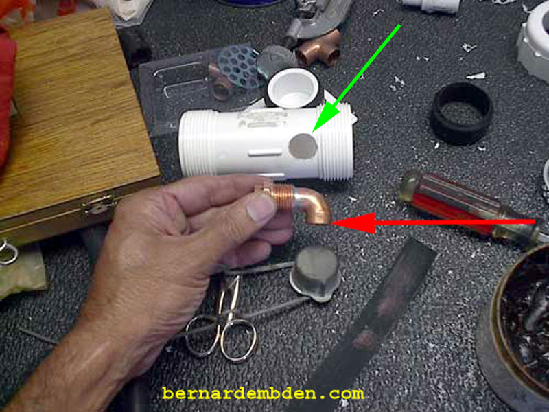
(Photograph below) This modified fitting is screwed into the body of the housing with the elbow pointing down.

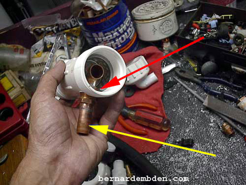
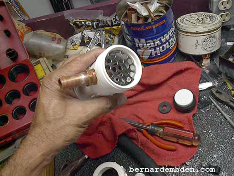
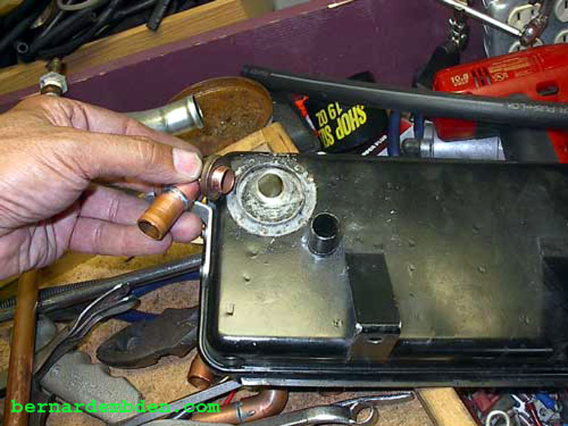
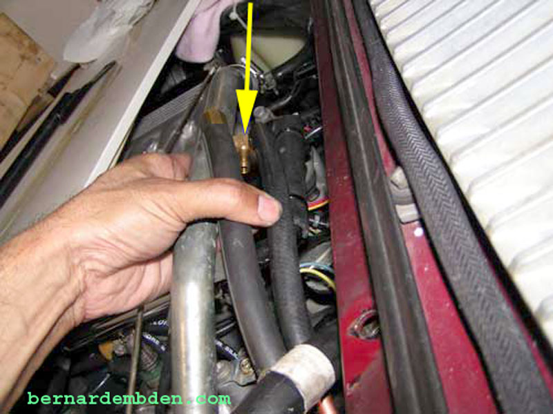
Photograph below. I modified a sink drain strainer by cutting a U section out to allow it to accommodate the fitting (red arrow). The strainer is then installed above the fitting. This is designed to hold the top filter air/oil separators in place when the filter is complete. A section of 1/2 inch copper pipe is soldered to the fitting to accept the crankcase vent hose. (yellow arrow).
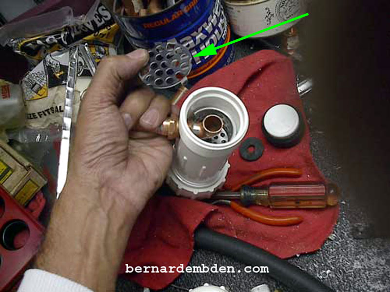
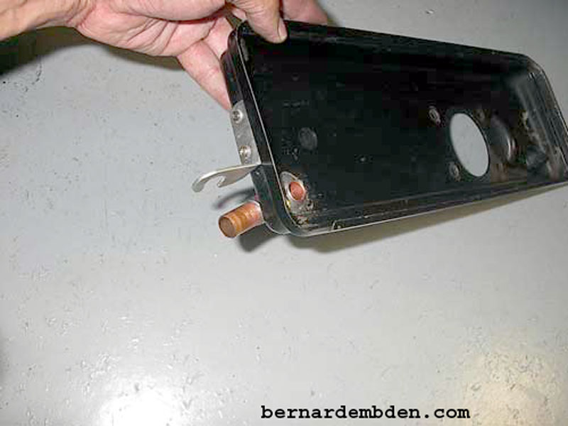
I then modified a flat sink strainer (green arrow photograph below) to fit on the ridge at the bottom of the PVC housing.
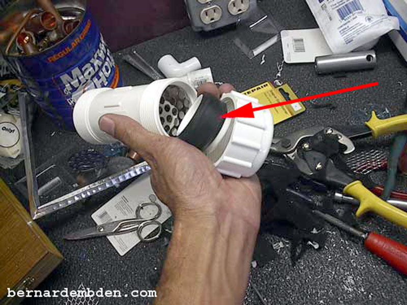
The bottom housing is then sealed with the PVC cap using the rubber sealing rings (red arrow photograph below) that came with the repair sleeve. This bottom space is designed as the initial, gravity enabled, air/oil separator chamber.
A generic sink strainer needed to be slightly modified to fit in the top portion of the filter.
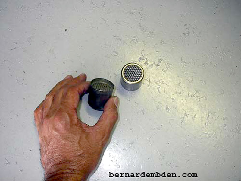
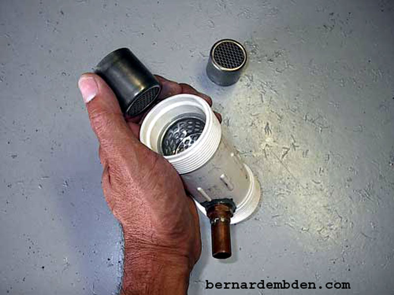
The Jaguar V-12's current PCV system comes with an air/oil separator (AOS). It is located in the crankcase PCV breather elbow that the PCV pipe attaches to at the front of the engine. I purchased two identical air/oil separators from Coventry West.
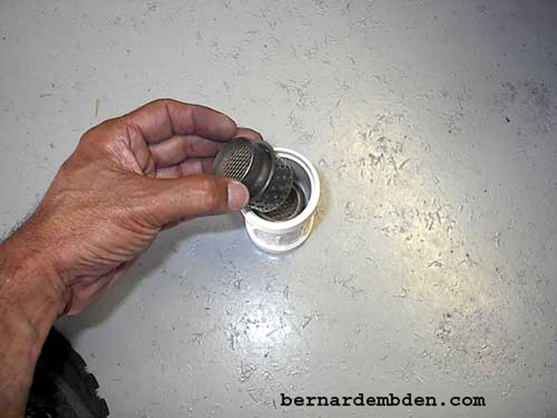
(Photographs below) I installed both AOS in series in the top portion of my filter. The modified strainer holds the second air/oil separator and seals against the sides of the custom filter housing, ensuring that all crankcase blow-by goes completely through both air/oil separators.
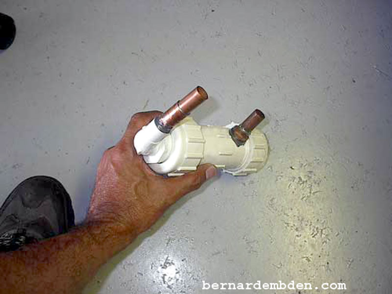
Photographed below is the final mockup of the Custom air/oil separator filter. I drilled a hole in the top end cap and cemented a 1/2 in PVC fitting to the cap. I used JB Weld as thread sealers to ensure a pressure tight assembly. The separator/filter is designed with three compartments. The lower first compartment is a gravity oil/air separator. The blow-by will then be drawn through two distinct air/oil separators by engine vacuum. The filter is not designed to handle significant pressure, however it must be pressure tight. Test by plugging the top outlet and applying 5 psi to the inlet. It should not leak.
Not wanting any vacuum restriction to the air/oil separators, I decided not to use a PCV valve in this installation. After removing the top cap I used copper pipe to solder a number of fittings together to reduce the pipe size from 1/2 to 3/8 inch. (photograph below) The modified cap is then reattached to the top of the AOS using the rubber sealing ring.
The next issue was to modify and improve the existing PCV system. The Jaguar V-12 engine has no "flow through ventilation" of the crankcase. Vacuum is applied to the crankcase in a (T) connection at the left air cleaner assembly. Curiously, the diameter of the opening at the air cleaner filter housing, (at the junction of the crankcase vent pipe and PCV valve), is as large as the crankcase vent pipe (1/2 inch I.D.) This somewhat unique configuration, along with the requisite PCV valve, limits the amount of vacuum applied to the crankcase, maintaining more of a slight pressure differential relief "flow" that any tangible vacuum. The system seems to be designed to allow positive crankcase pressure someplace to go, rather than a reactive approach of relieving crankcase pressure.
I junked the existing PCV system.
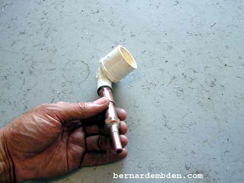
I fabricated a 1/2 inch copper transition pipe. (photographed below). The top end (red arrow) is 3/4 inch and will connect to the rubber cap at the engines PCV crankcase breather elbow. The small 3/8-inch nipple (yellow arrow) is for monitoring vacuum strength in the system. The end of the copper pipe (green arrow 1/2 inch) will connect to the inlet side of the custom air/oil separator filter.
I removed the PCV valve and housing from the left air cleaner assembly and brazed in a 1/2 inch copper elbow. This would be the filtered air inlet source for the new PCV system.
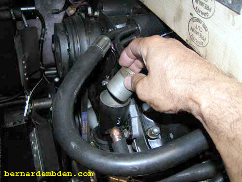
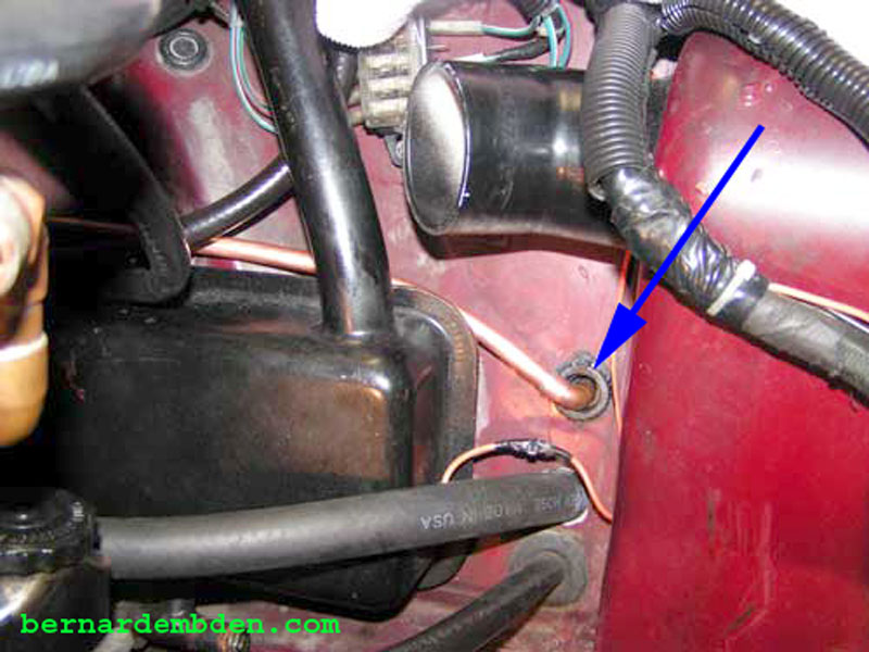
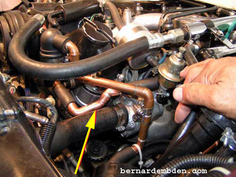
The next step was to remove the PCV breather elbow from the front of the engine. A Torx wrench is needed for these fittings. (red arrow photograph below).

I drilled a 1/2-inch hole in the side of the elbow. The location is critical. It must be the flat side of the elbow facing the left side of the engine.
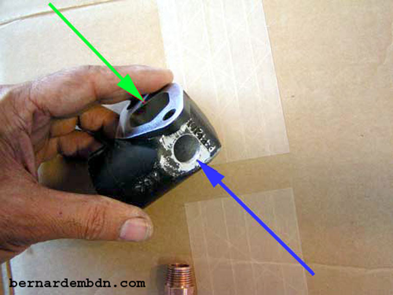
Note that the modified PCV elbow breather has the opening to the crankcase (green arrow) significantly larger than the new 1/2-inch hole. (blue arrow) This means that, everything else being equal, there is always more vacuum being exerted against the crankcase opening than the 1/2 inch filtered air source.
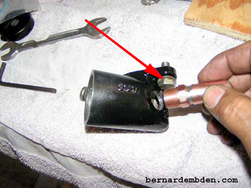
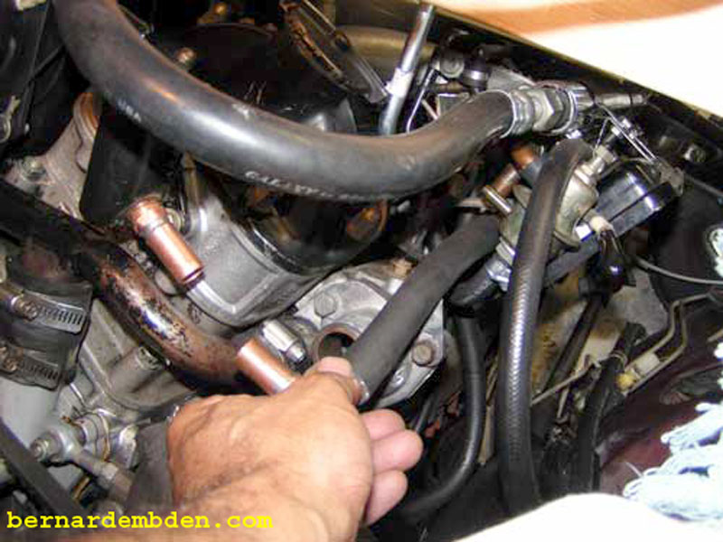
Tap the hole to accept a modified 1/2-inch copper pipe fitting. Note that the location of this new fitting will prevent one installation bolt from being installed. I substituted a regular bolt and installed it in the breather elbow (red arrow photograph below) before I screwed and tightened the copper pipe fitting to the modified elbow. Make sure you use thread sealer at this connection.
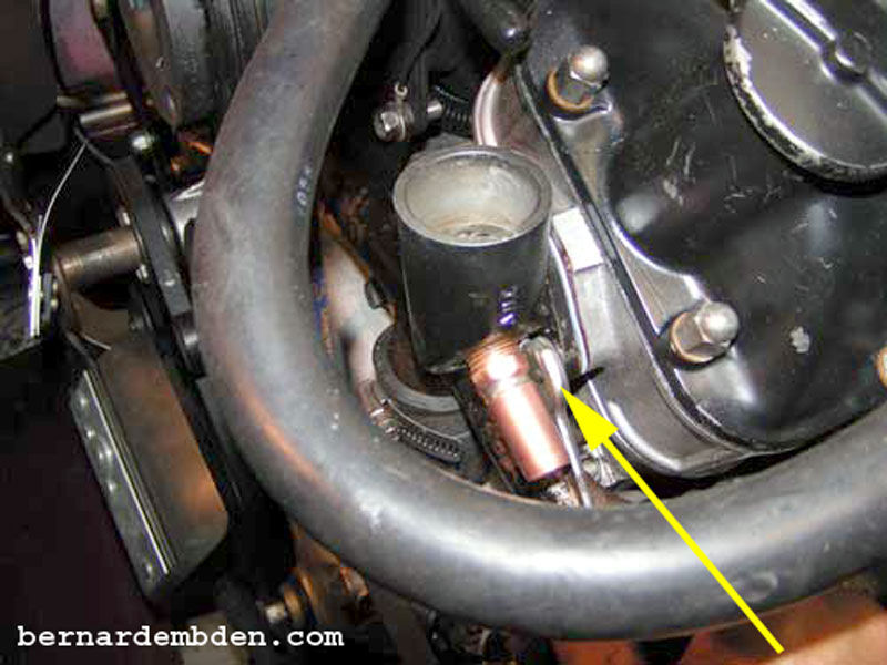
Using a new gasket, the modified breather elbow is then reinstalled onto the engine. Note pre-installed bolt (yellow arrow photographs below).
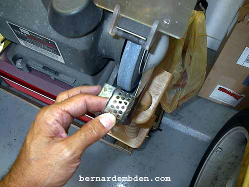
Clean the original air/oil separator and re-install in the engines PCV breather elbow.
The objective of this project is not to install a modern PCV flow through ventilation system. I had no intention of removing and tapping the valve covers. Rather, the objective is to expose the crankcase to tangible, constant engine vacuum, similar to a flow through PCV system. This would require a source of filtered air. I connected the modified breather elbow fitting to the left air cleaner fitting that was fabricated earlier. The new PCV system will pull filtered air from this source. Without this small filtered air source there would be the danger of applying too much vacuum to the engine crankcase system.
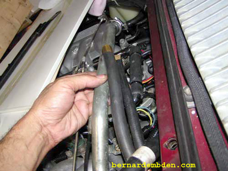
The custom transition pipe is installed to the PCV breather elbow rubber cap. The other end will be connected to the inlet side of the custom separator/filter. I fabricated a bracket to secure the transition pipe to the engine (green arrow).
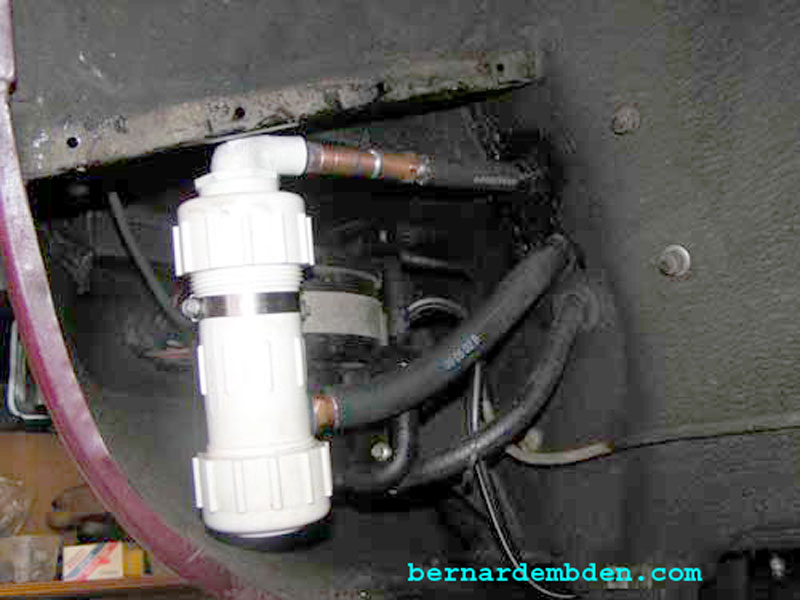
This filter was always designed to be installed outside the engine compartment. The logical location is with the charcoal canister in the front of the left fender compartment. Remove wheel and access panel. I drilled two holes approx. 1/4 inch above the existing hole that connects to the charcoal canister. The bottom hole is larger to accept a 1/2-inch I.D. hose. The top hole will accept a vacuum sourced 3/8-inch copper pipe. Relays and the expansion tank are in the vicinity, make sure the engine compartment is clear before drilling. Prime the exposed metal surface of the holes to prevent rust.
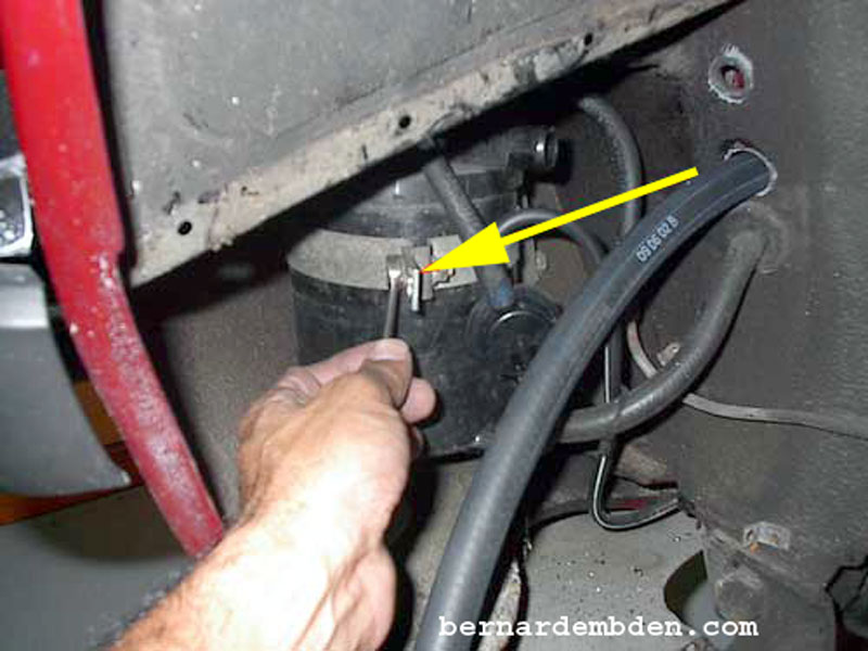
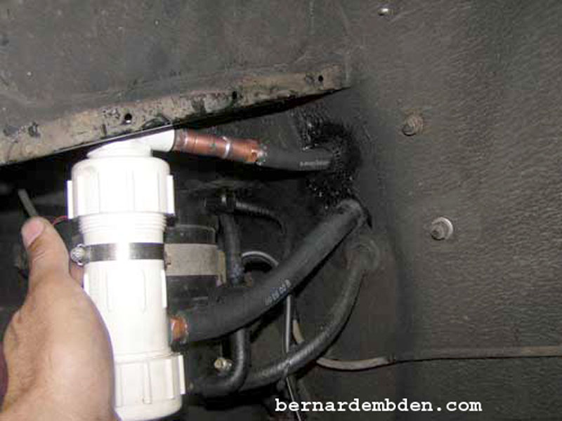
The 1/2-inch crankcase vent hose is routed through the bottom hole in the front fender compartment. I installed a bracket attachment on the existing charcoal canister bracket in order to mount the air/oil separator. (yellow arrow).
Instead of using hose for my vacuum source inside the engine compartment, I soldered an elbow on 3/8 copper tubing to connect to my custom AOS filter. (blue arrow).
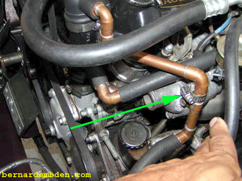
In order to balance the vacuum between engine banks I brazed another fitting at the center of the balance tube. (yellow arrow photograph below) I transitioned the 3/8-inch copper tubing to hose and connected it to this fitting. This would be my vacuum source for this project.
I could just tie wrap the filter in place, but my modifications should not only work, they must look professional. I modified a small bracket to accept a hose clamp and bolted it to the existing charcoal canister bracket.
Connect bottom hose from the engines PCV pipe (crankcase). The top connection goes to the 3/8-inch engine vacuum copper tubing. Tighten hose clamp to hold the filter vertically in place.
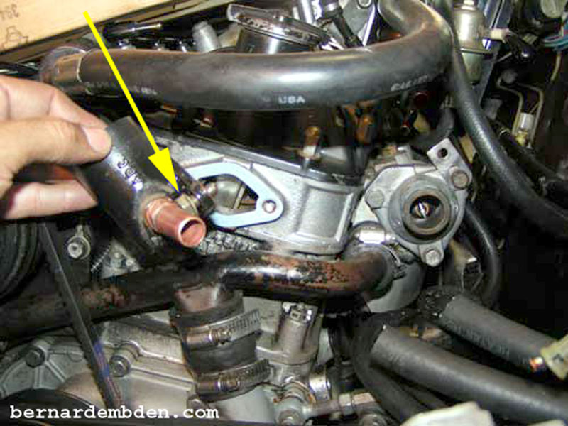
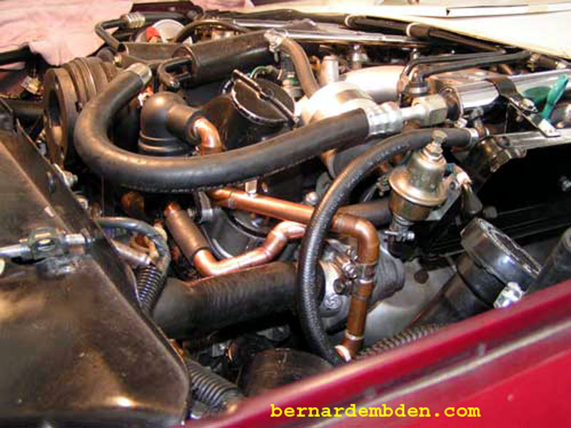
Attach hoses inside the engine. During the final installation, I fabricated copper pipe (yellow arrow photograph below) to connect the PCV elbow breather to the filtered air source in the air cleaner assembly (because it looks better).
The PCV air/oil separator filter is designed to function as follows :
Engine vacuum, sourced at the center of the balance tube, pulls filtered air from the left air cleaner connection through the PCV breather elbow and air/oil separators in the custom filter. As the air is pulled through the PCV breather elbow, the crankcase orifice inside the elbow exposes the crankcase to engine vacuum. If there is no positive pressure in the crankcase, the vacuum pulls all the needed air volume completely from the filtered air source in the left side air cleaner assembly.
Once positive pressure appears in the crankcase that pressure is immediately relieved by the vacuum. Because of the PCV elbow's larger opening to the crankcase, the vacuum will always "look there" first. The engine's crankcase is never exposed to too much vacuum, as the filtered air feed tube constantly provides the necessary additional air volume necessary from the air cleaner assembly. This ensures that the crankcase is always exposed to constant, tangible, negative pressure at the PCV breather elbow under all conditions.
As the blow-by is drawn through the custom filter the air/oil separators extract the majority of oil particles. The blow-by then enters the intake manifold at the center of the balance tube, maintaining vacuum balance in both manifolds and ensuring that any blow-by is burnt equally by both cylinder banks.
I believe this customization is a significant and worthwhile improvement over the stock system.
Crankcase air/oil separator filter project completed.
Replace fender compartment access panel and front wheel. At each oil change interval, filter will be disassembled, air/oil separators cleaned and reassembled.
Expect to spend a couple of days on this project. if you have visible blow-by, the combustion chamber and plugs of your engine should stay cleaner. In addition, the PCV system will actually work.
