
My 25 year old starter was becoming a problem. When hot it became reluctant to turn the engine over. Symptoms indicated that the solenoid was the culprit. If I went through the trouble of taking that bad boy out, I was going to put a new, and improved, one in.
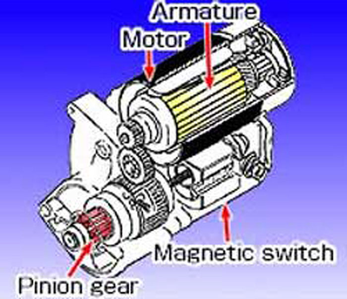
Starter technology has not made great strides since 1978; however I was intrigued by the current gear reduction starters. The concept was simple. A small high-speed motor mated to a gear reduction system reduces the rotating speed of the armature to 1/3 - 1/4, which then rotates the pinion gear. The result: A stronger and lighter starter than the original that consumes less current and requires no permanent modification to install in my vehicle.
Essentially a win win win situation.
After some research I decided to purchase my starter from www.britishstarters.com . This company mates a 1.2 HP Nippondenso gear reduction starter (diagram photographed below) to a custom fabricated front plate that bolts to the V-12 bell housing. This starter is remanufactured by Gustafson Machine, a facility in Gloucester Ma. The solenoid, bearings and windings are replaced and exterior re-plated. Cost. approximately $200.00 US.
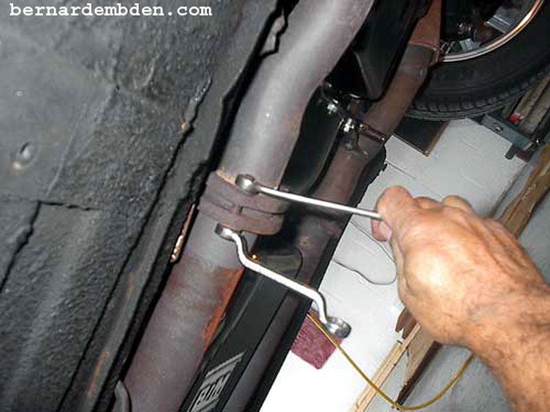
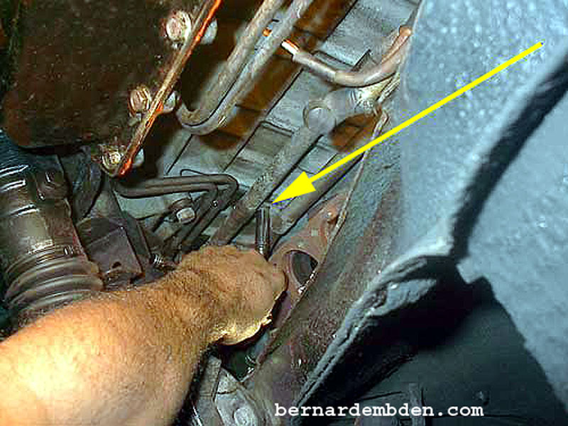
The photograph below starts the project. Remove exhaust pipe connection. In the absence of a lift, jack the car up, preferably with all four wheels off the ground and supported with appropriate jack stands. Be safe. You will be under the car for a while.
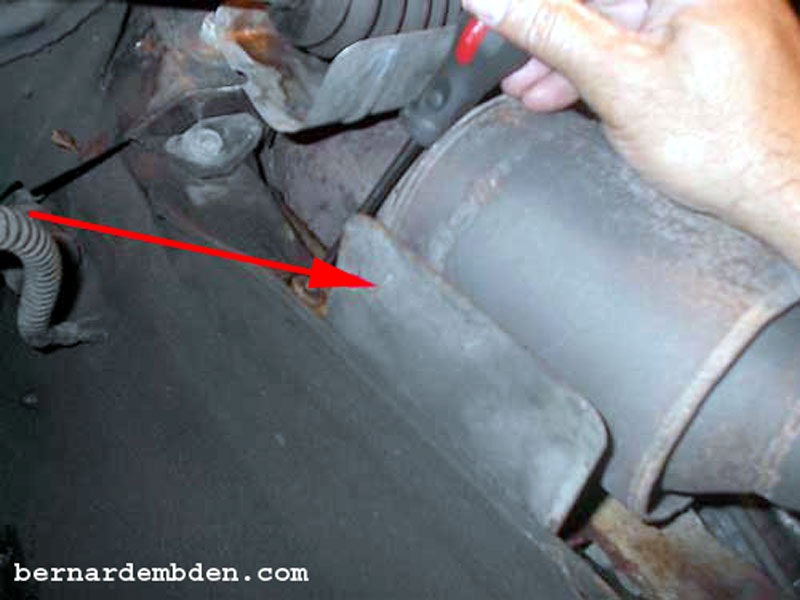
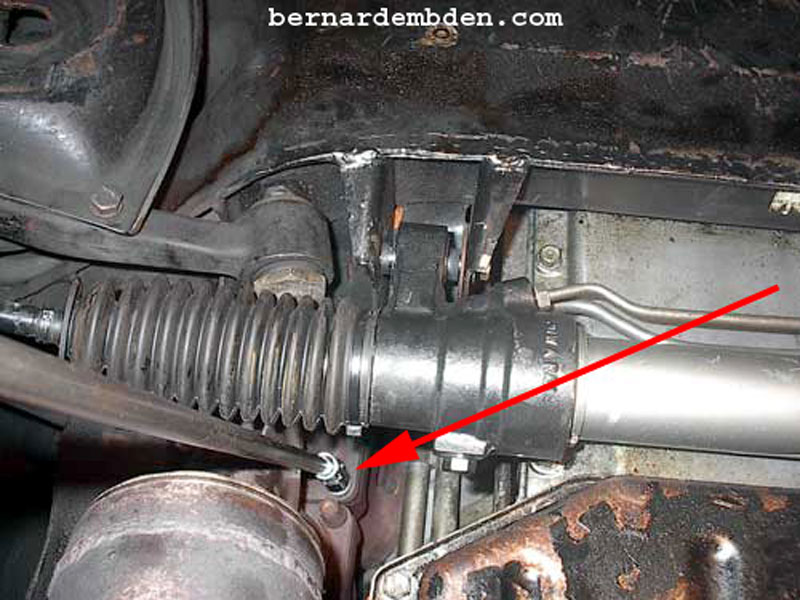
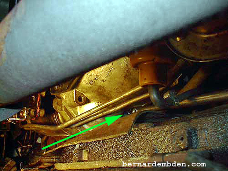
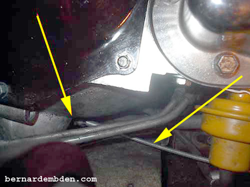
Remove the right side exhaust heat shield. (red arrow photograph below).
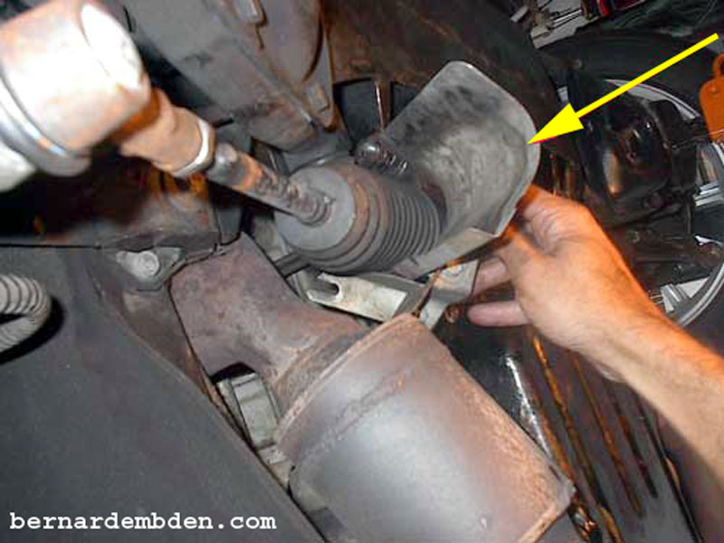
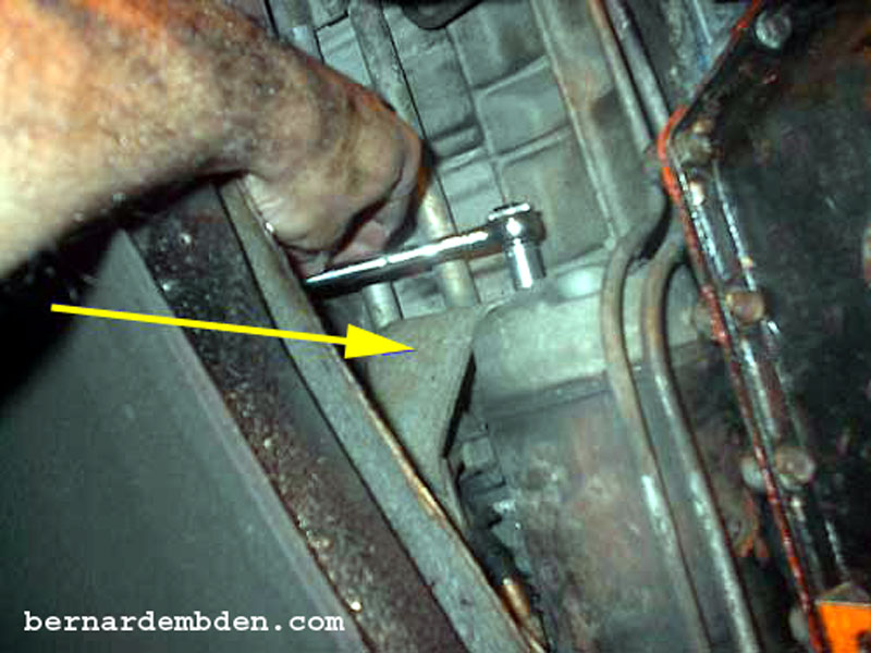
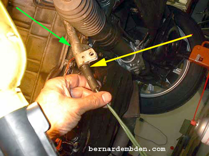
Also the steering rack heat shield. (yellow arrow photograph below). Note that on right hand drive models the complete steering rack has to be removed.
Fair warning. To complete this project you absolutely must have a long 3/8 extension with 12 point 9/16-inch and 12 point 7/16-inch universal sockets. .
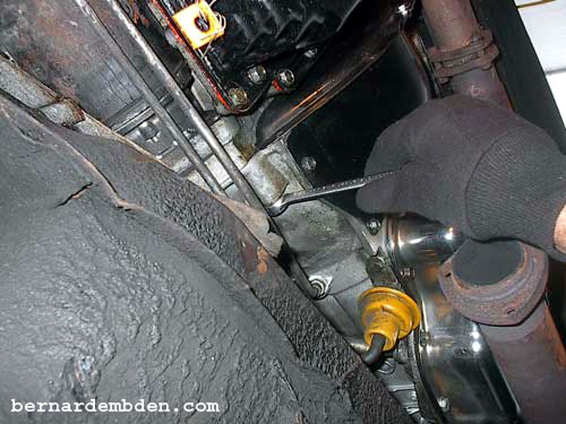
All the nuts that attach the exhaust down pipe can be accessed from below the vehicle. Position the 9/16 socket and extension either side of the steering rack as needed. (red arrows photographs below).
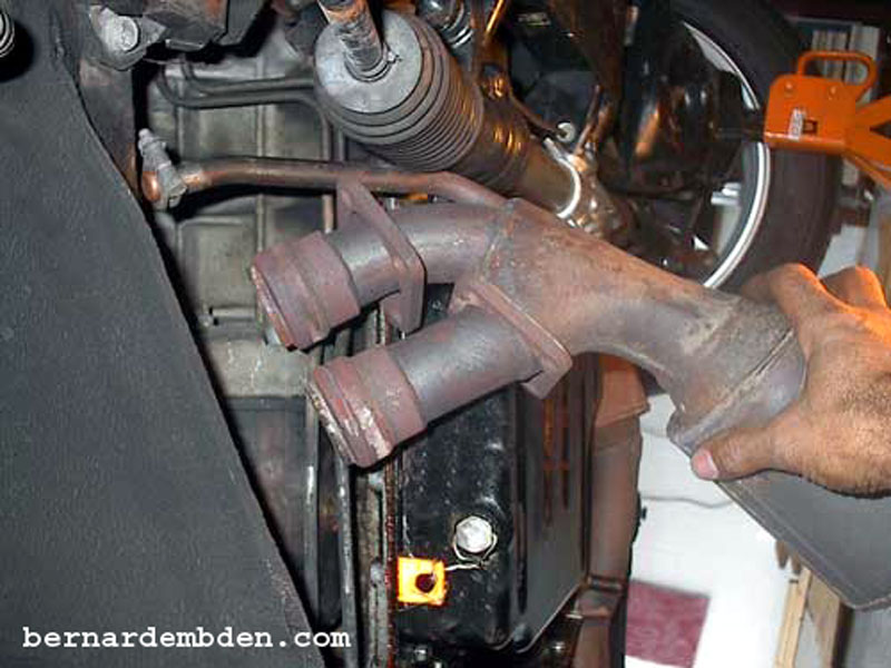
Remove exhaust down pipe. Be careful not to damage or nick the sealing surfaces.
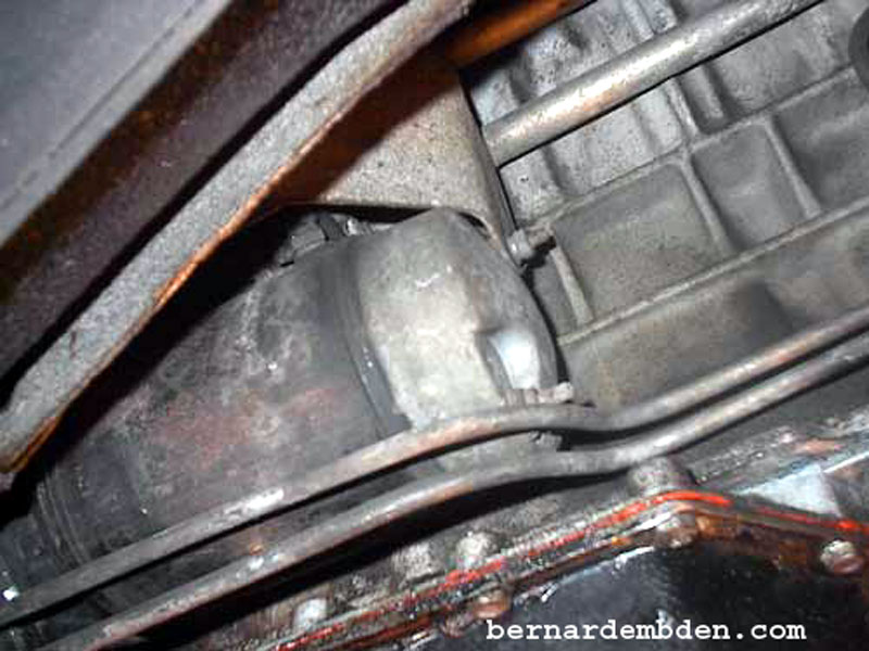
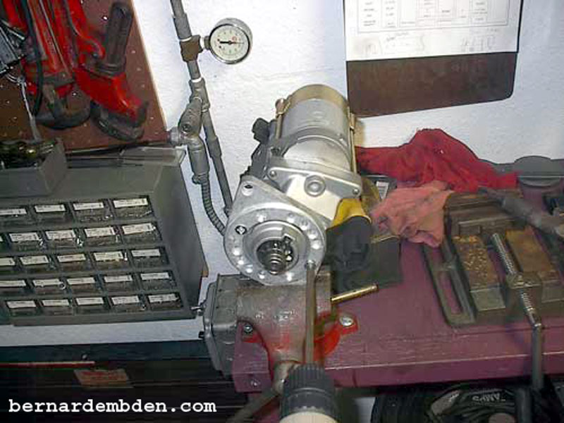
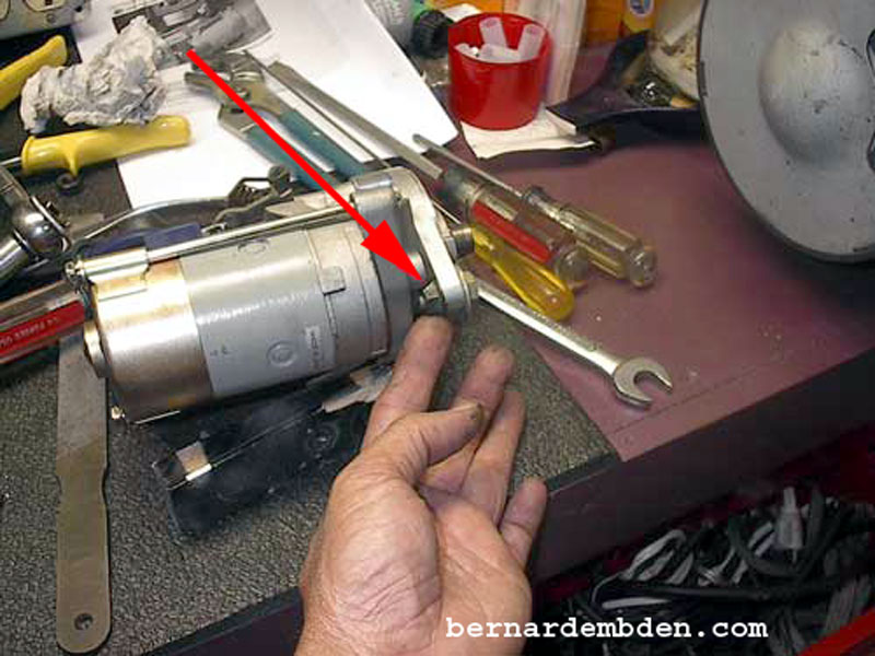
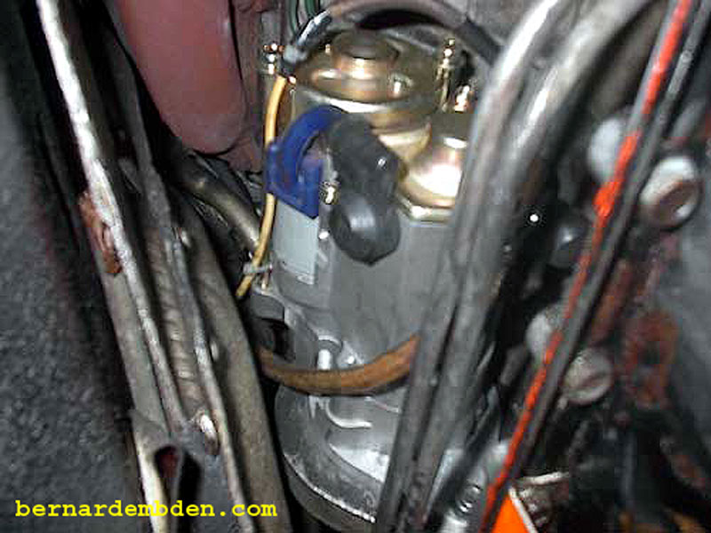
In the photograph below the bad boy 25 year old starter is now actually visible.
Remove bottom starter bolt. (this is the easy part).
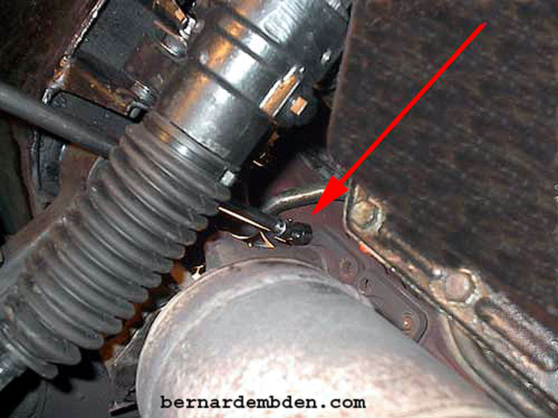
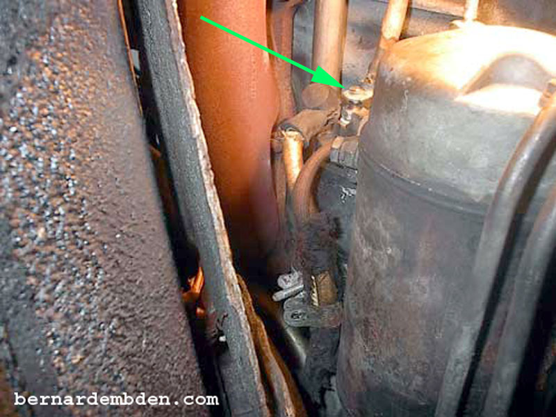
The infamous XJ-S V-12 starter's top bolt. This is the bolt that will make grown men cry and drive sane men to consume alcohol. It is just barely visible and recessed in the bell housing casting. It can only be removed with a 12 point, 3/8 drive 7/16-inch universal socket attached to a long extension. (green arrow photographed below). Don't even try anything else. You must get an absolutely good fit with the socket before applying pressure. Hammer it on lightly if necessary. If you round off or damage this bolt head you will require therapy.
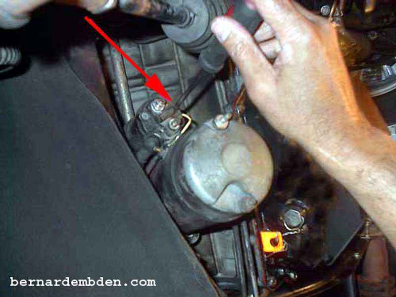
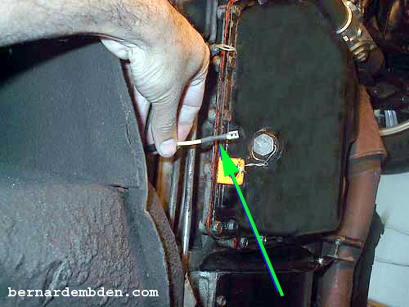
Remove heat shield from the old starter's solenoid. (yellow arrow photograph below).
Remove nut from large cable to starter solenoid. (green arrow).
(Red arrow) Remove wire that triggers the starter (from starter relay).
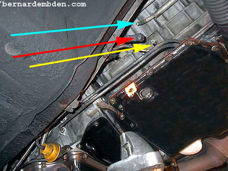
Wires removed from the starter solenoid are identified in the photograph below.
Light blue arrow from the alternator. (actually two wires under a single sheathing).
Red arrow from the battery bus.
Yellow arrow from the starter relay.
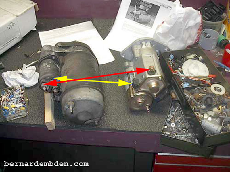
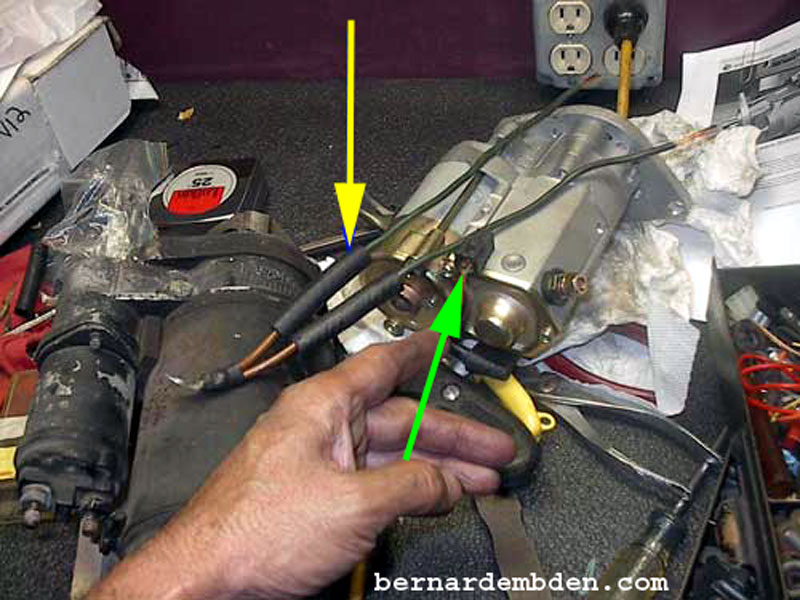
Comparison of the two starters reveal a significant difference in size and weight. The alternator and battery bus connections are identified by the red arrows. The yellow arrows identifies the starter relay connections. Arrows point to correct connections on both starters.
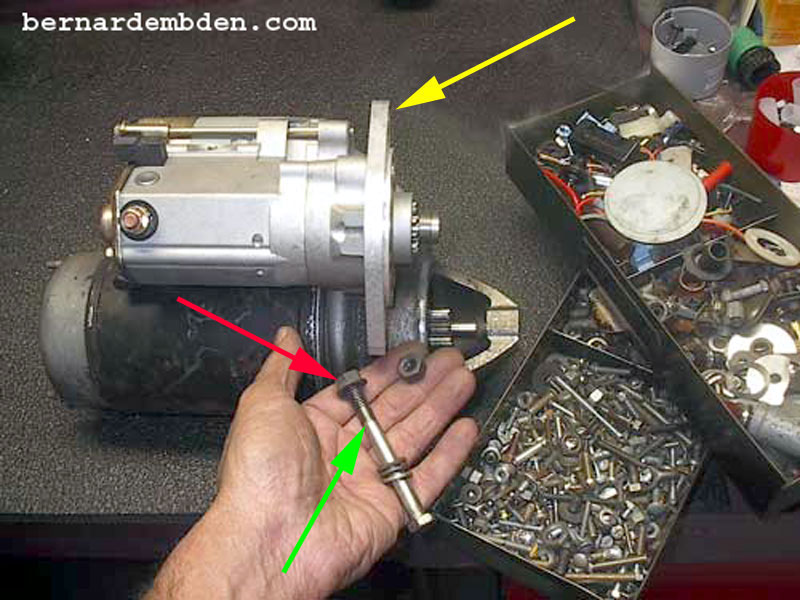
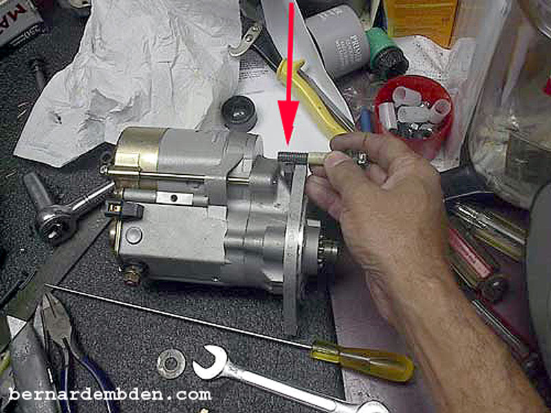
(Photograph below) The new starter's custom plate is not threaded. (yellow arrow). Therefore it cannot accept the old threaded bolt. (green arrow). A suitable nut must be used. (red arrow).
The starter might have to be rotated (clocked) to fit. If necessary, remove the custom plate.
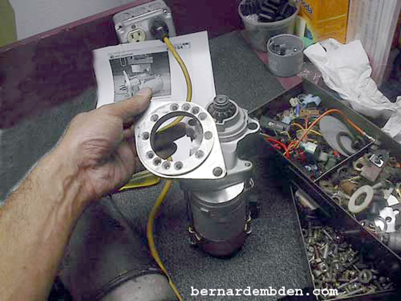
With the plate screws removed, trial fit the starter to the engine. Mark the plate location, and refit with Loctite on the bolt threads. Although unverified, the manufacturer claims that the plate will only work with the marked side towards the engine block, maintaining that it cannot be rotated 180 degrees.(see manufacture instructions).
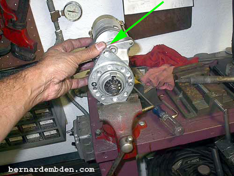
This is the plate orientation that I wanted. Note that the top bolt hole's location might not allow the original top bolt to extend before hitting the body of the starter. (green arrow photograph below) In addition, it would be all but impossible for one person to attach the top bolt.
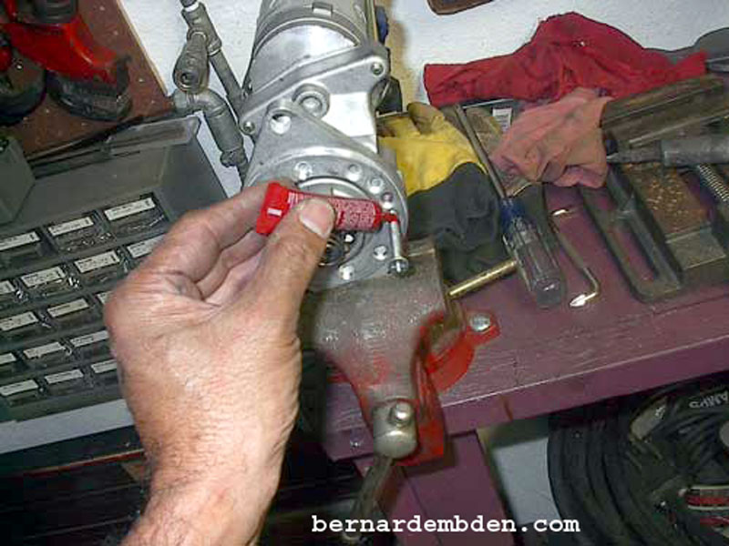
Taking a tip from Phil Grey I sourced a nut that fit the existing starter's top bolt threads. I then cemented the top bolt's nut to the starter. (red arrow photograph below). Any cement that hardens will work. I left it overnight to dry.
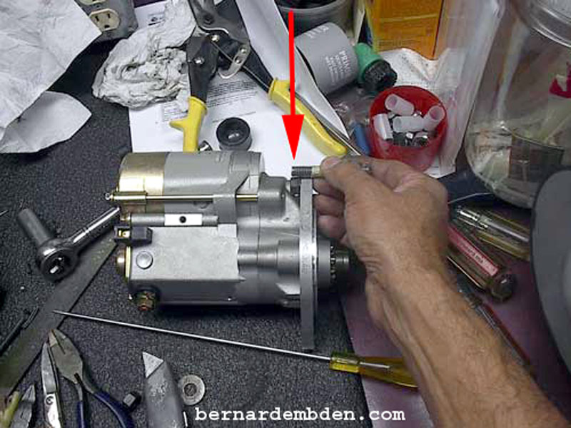
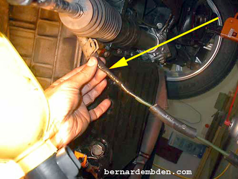
I used the starter's top bolt to determining how much the bolt extends from the bell housing to the starter. Using that measurement, and taking into account the starter plate and glued on nut, I determined how much to cut the top starter bolt. (red arrows photographs below).
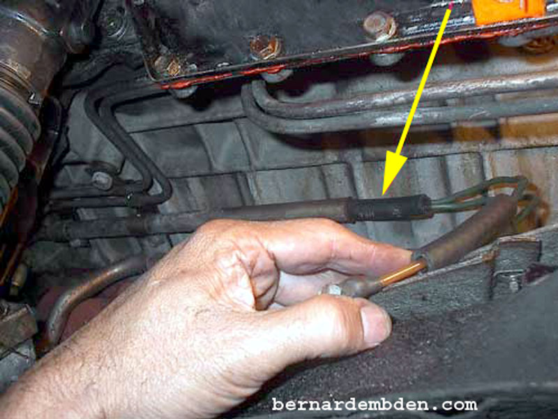
With the new starter now clocked and ready, the wires from the alternator must be lengthened. I removed the conduit that the alternator wires go through. (yellow arrow).
This allows me to lower the wires where I have easy access to them. Cut both wires in a convenient place. (don't be scared or confused you have come this far).
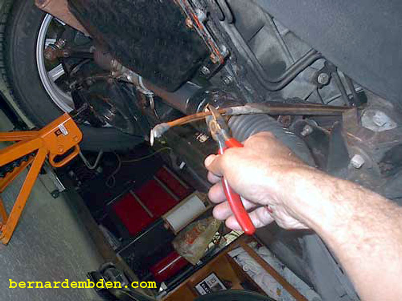
(Photograph below) You will need to lengthen both wires approximately 8 inches. (You can use one heavy gauge wire.) Due to the hostile environment, I used heater hoses to insulate my solder joints. (yellow arrow). The green arrow identifies the starter relay connection.
(Photograph below) I wanted the other connection to fit inside the conduit. I used a small copper sleeve to solder the two wires together. A soldering iron will not work for this. You will need real fire. A torch set to a low flame is ideal.
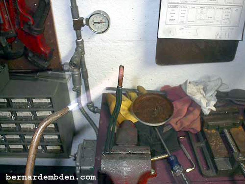
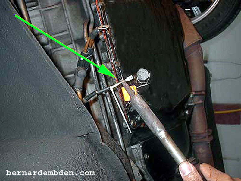
Duplicate the soldering procedure on the wires from the alternator. Tape joint. (yellow arrow).
I used a heater hose to augment the insulation, (yellow arrows photograph below). I then forced the connection back into the original conduit. (green arrow). The wires are then reinstalled in its original location. .
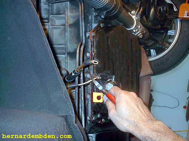
The next step is to change the original (bolt and nut) starter relay connection to a spade connection to fit the new starter. Cut, solder and heat shrink. (green arrows photographs below).
Getting the top starter bolt back in through the bellhousing was no easy chore. I used a mechanical, flexible claw to hold and guide the bolt.(yellow arrows photograph below).
Install and tighten top and bottom starter bolts and nuts. Route and secure wires away from exhaust. Check starter operation before installing exhaust down pipe.
Tiny starter sounds different, but even with less than a fully charged battery,
it starts every time!
