
It is not terribly difficult to connect a battery maintainer (trickle charger) to the Porsche Macan. However it’s virtually impossible to connect a battery maintainer to the Macan without leaving the hood, windows, or tailgate open.
This then was the challenge.
My first thought was creating a connection port in the lower opening of the front bumper. I could then connect to the jump start studs in the engine compartment. However the longer I looked at the front bumper configuration the more I realized that for me, this was not the ideal location.
A battery maintainer connection at the front of the vehicle would require the cable from the maintainer to string across the front of the vehicle to the garage wall where it would be plugged in. This would create an issue as, to get to my work bench I would have walk in front of the vehicles parked in the garage.
A solution was to install an electrical receptacle in the ceiling of the garage and power the charger there.
That thought lasted about 10 seconds before I discarded it as a terrible idea. Apart from looking horrible, the idea that I would need a ladder to plug in the battery maintainer was just stupid.
At this point I thought of what would be a clean sheet design. Essentially if I were designing a charging port where would I put it?
The answer always came back the same. In the rear of the vehicle.
The most logical location was somewhere in the cargo area, but this presented its own issues. A connection in the cargo area would require the rear hatch to be partially open. While this was possible in a non-power locking hatch, the Macan power locking mechanism would invariable crush the wires against the weather sealing gasket. For me that was a bridge too far.
The more I thought about it I kept coming back to one location.
Behind the rear license plate.
Bloody brilliant, this then was the location for this project.
Years ago I remember cars with gas tank fillers accessed by tilting the rear license plate bracket. I quick check of the internet indicated that these tilting plate holders still existed. They were no longer used on the rear to access gas caps, but were popular with the off-road community to swing up front license plates to access front mounted winches.
A call to etrailer.com and a spring return fold down license holder was in the mail.
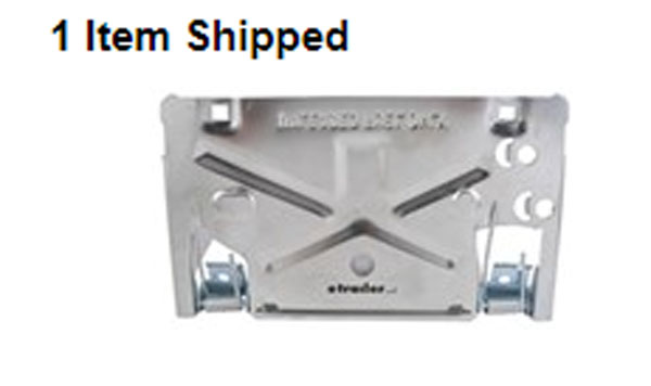
Examination of the product indicates it was quite sturdy and well built. One issue however was that the two torsion springs were too damm strong. Apparently this product is designed to mount to a steel bumper or structure. The polyurethane like material of the Macan diffuser that the rear plate mounts to might not support the repeated "flipping" of the plate holder.
The first modification was easy. I removed one of the torsion springs. The second modification would be to fit a metal backing plate that the mounting holes would attach to.
Time to order stuff.
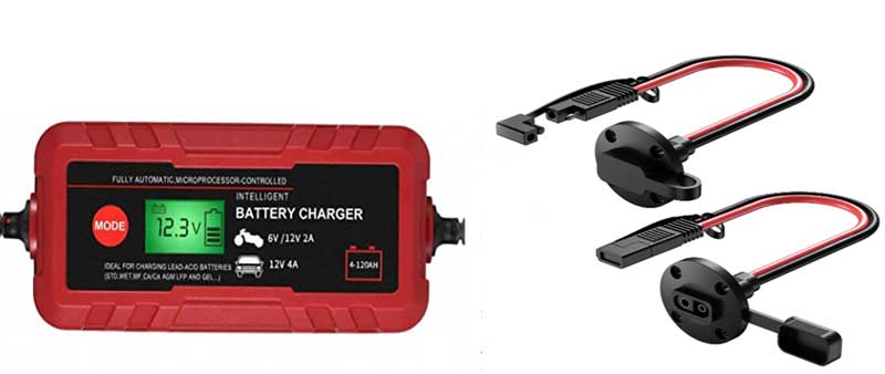
Adakiit 4 Amp smart Battery maintainer/charger for lead acid and AGM batteries. Connection ports and cabling designed primarily for motorcycles. extra cables, connections, circuit breaker, weatherproof grommet etc.
Why not a more expensive battery maintainer? I currently have the Adakiit unit on another vehicle for a number of years and I have been satisfied with the product.
First decision was whether the plate was going to flip up or down. This is a critical decision, as behind the diffuser somewhere there was a metal bumper. Its location would determine the location of the charging port which would determine whether the plate flips up or down.
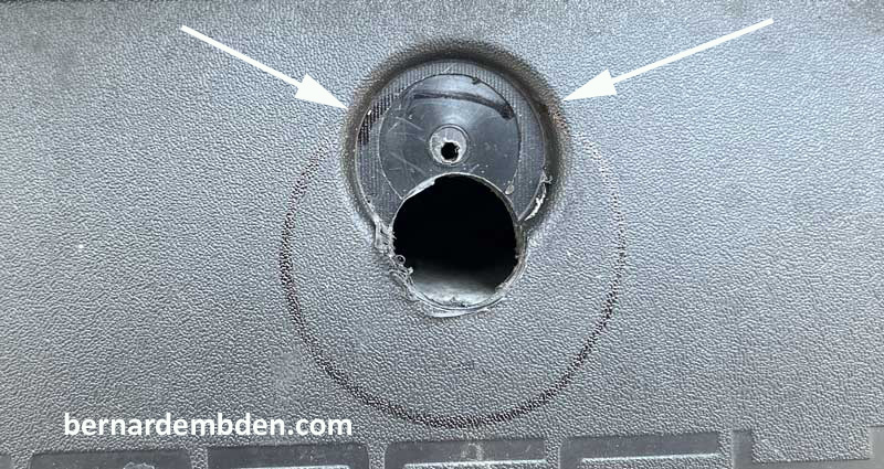
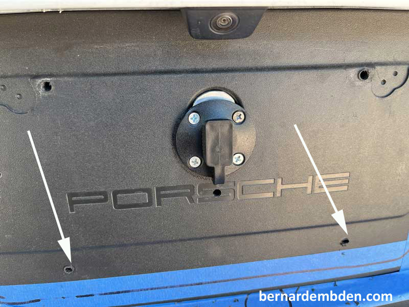
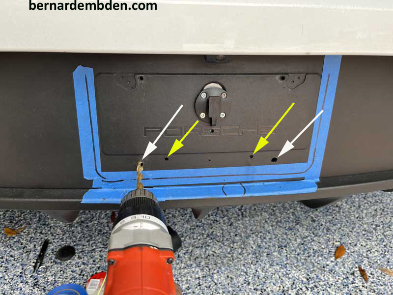
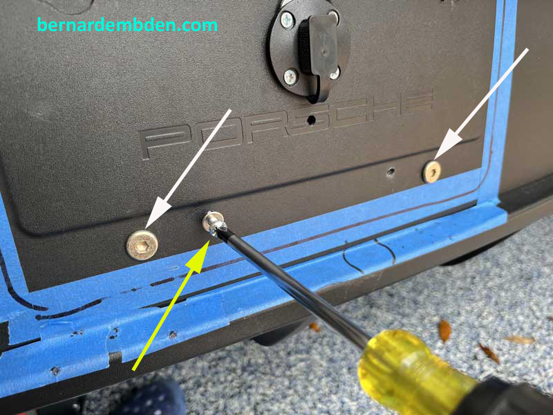
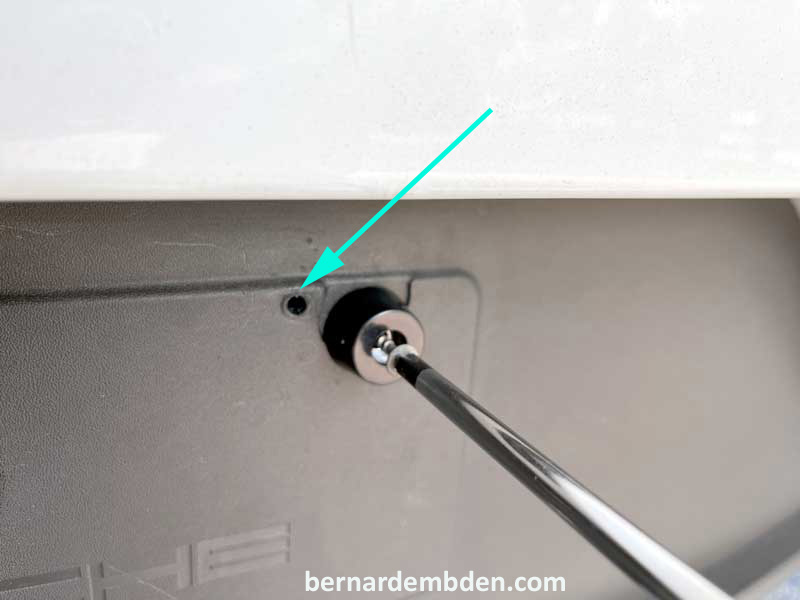
I drilled a couple of small holes in the rear diffuser plate location so you don’t have to.
The red arrows indicate the existing screw holes for the license plate, The white and green arrows are the exploratory holes that I drilled.
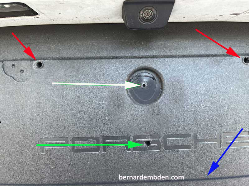
By inserting a wire probe through the openings I determined the following :
1) Top of the rear bumper bar is approx. two inches below white arrow.
2) There is a direct path from the top of the diffuser (red arrows) to the battery compartment.
3) Approx. 3/8 inch space between bumper face and diffuser (green arrow)
4) Bumper bar width ends at approx. diffuser line indentation. (blue arrow)
.The plate location and flip orientation was now determined. The charging port would have to be mounted above the bumper with the plate hinges attached below the bumper.
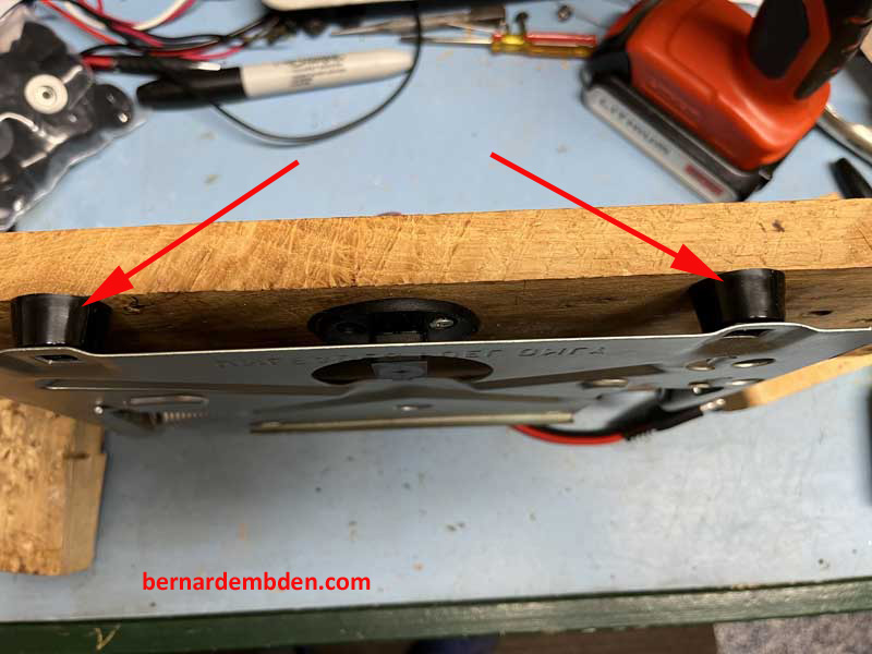
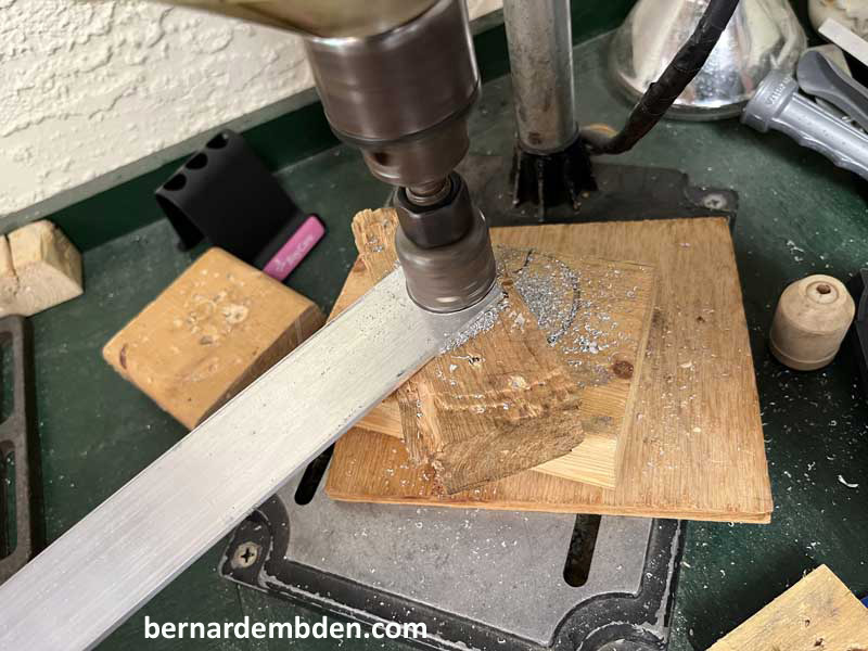
Transferring my measurements to some wood stock allowed me to mount the flip plate with the charging port already installed in the required location. (torsion springs removed temporarily, photograph below).
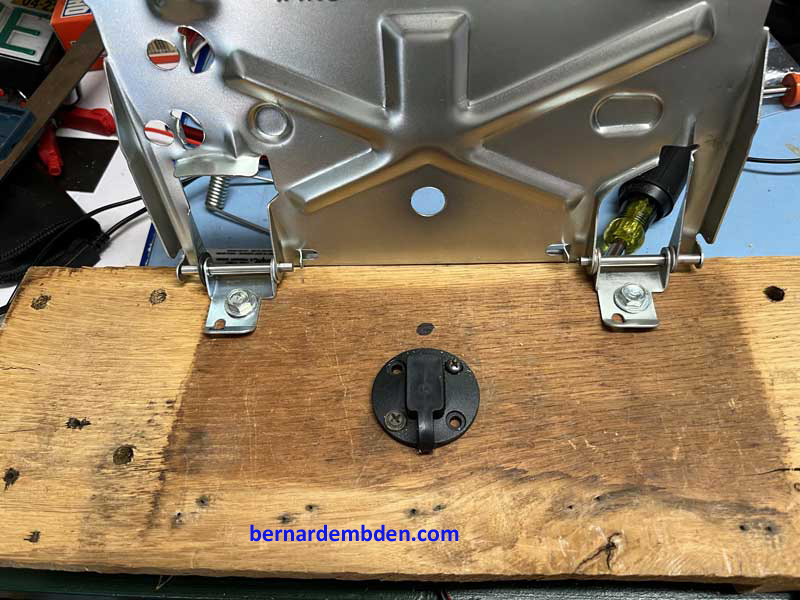
We have a problem. In the closed position, the charging port (approx. 1/2 inch high) prevents the plate from sitting flush. (red arrow photograph below)
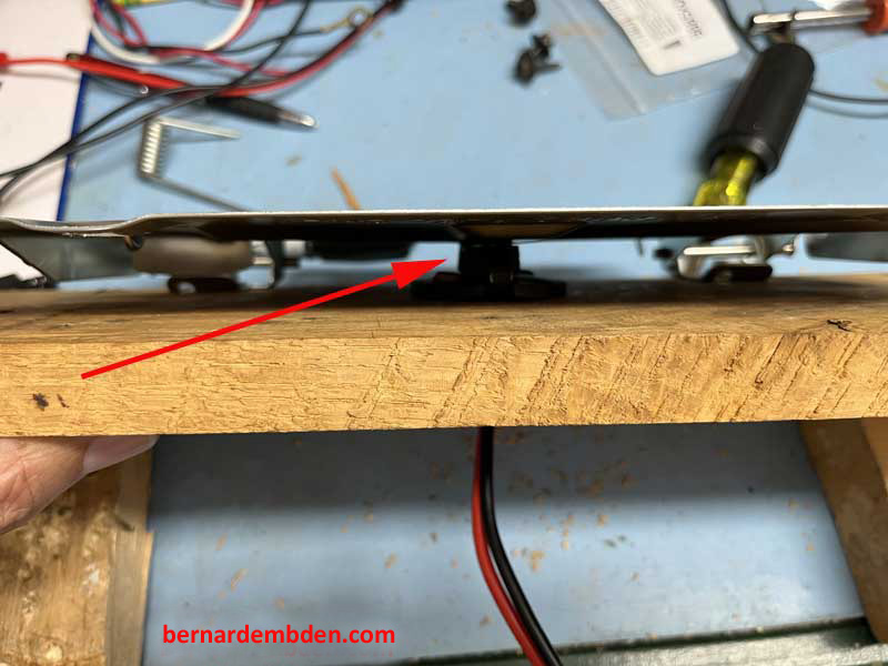
The solution would be two fold.
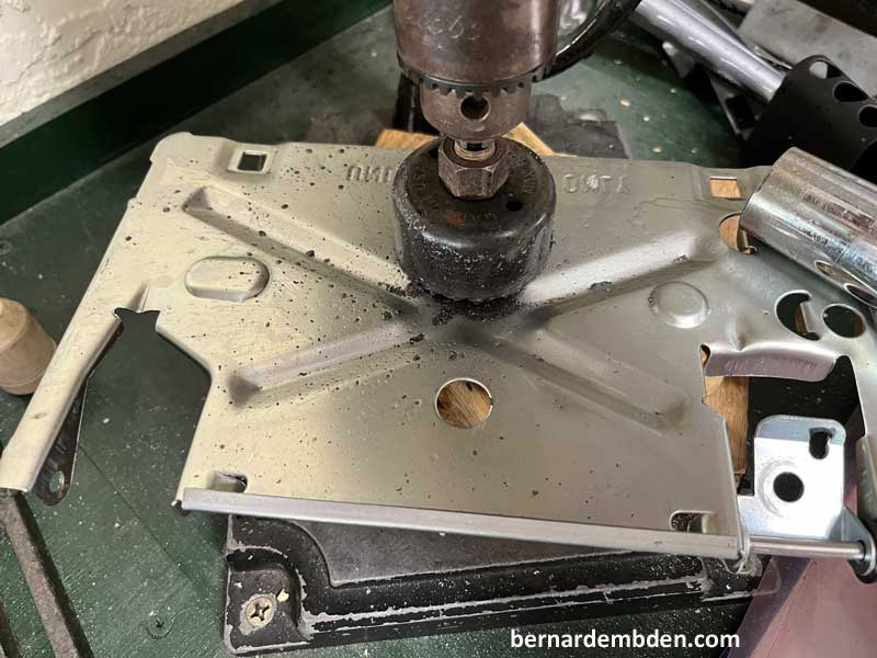
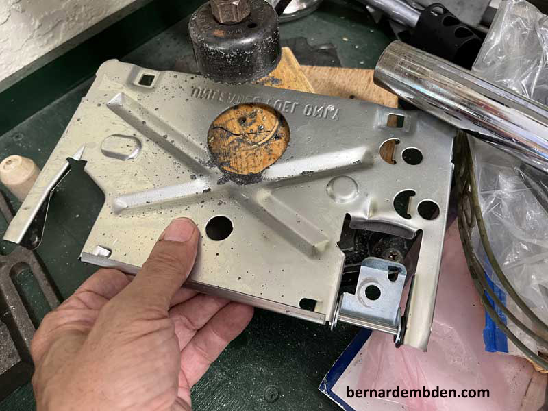
1) Cut a 2 inch hole in the flip base for added clearance.
2) Install 1/2 inch rubber standoffs (red arrows photograph below).
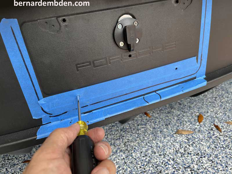
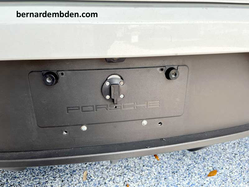
Enough of the chit chat. It was time to make some meaningful cuts in the diffuser. As a precaution a safe zone was taped out with blue tape. All mounting and drilling had to be within this zone which will be covered by the installed license plate. With the orientation and charging port location finalized, this information was then transferred to the rear diffuser license plate location.
It was time to start drilling some holes.
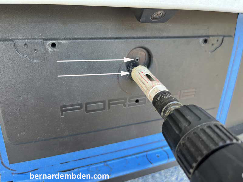
The outer face of the connection portal is approx. 4 inches in diameter. However the part that actually has the wires is only 1 inch in diameter. Based on my previous measurements the top of the rear bumper was two inches below my pilot hole. Using a 1 inch hole saw I drilled a hole centered one inch below the pilot hole. (white arrows photographs below).
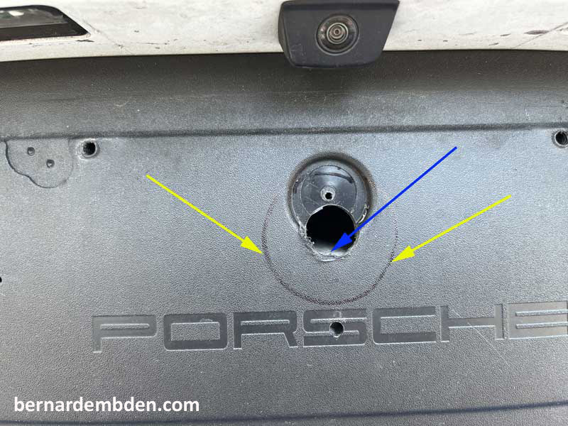
Photograph below. Note location of one inch hole. It is exactly above the top of the bumper (blue arrow). The yellow arrows indicate the location of the charging port's connection 4 inch flange.
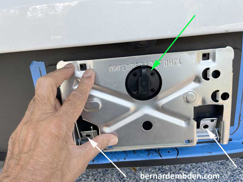
With the charging port flange now determined, (photograph below) offer up tilt plate, center around charging port (green arrow) and mark mounting bolts positions on the diffuser. (white arrows)
The location for permanently mounting the connection port flange to the diffuser was not ideal. The small indentation in the diffuser (part of the manufacturing process) created an uneven surface based on the location of the one inch hole. (white arrows photograph below)
I decided to fill this area with 1/8 inch aluminum stock. Using a hole saw, the same diameter as the indentation opening, I cut a round section from aluminum stock to fabricated the filler.
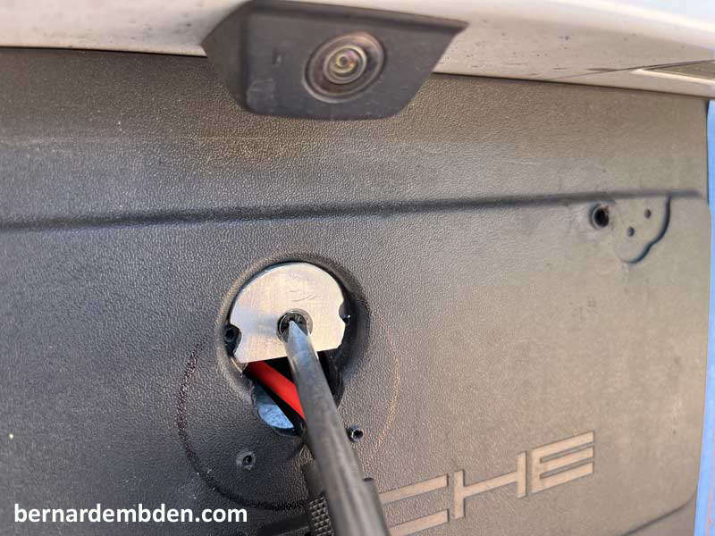
Connection flange installed Note holes for mounting the tilt plate holder. (white arrows photograph below)
To get to the battery compartment the spare, sub-woofer and the trim that covers the rear bumper has to be removed. The trim is secured via clips. Pull up on the trim like you rented the vehicle to remove it. Note that the spare is pretty heavy for a space saving spare. (or I am getting old fast) A rubber plug at the right side of the battery compartment allowed access to the battery compartment. This plug is installed from the diffuser side. Do not lose it as you will need it during this project.
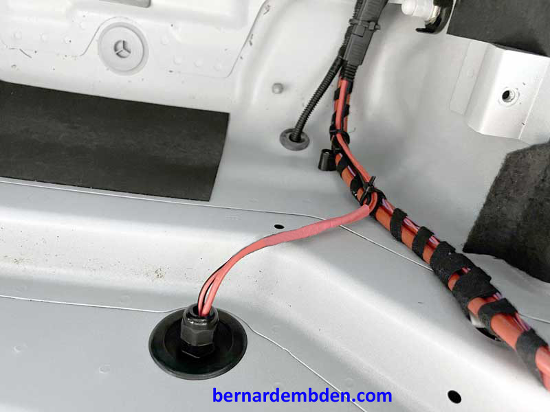
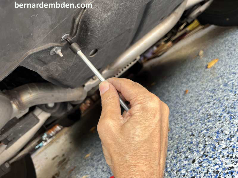
I snaked through this opening from the one inch connection hole in the diffuser. Note that some slack, along with a connection point, must be left behind the diffuser to facilitate future removal of the bumper/diffuser.
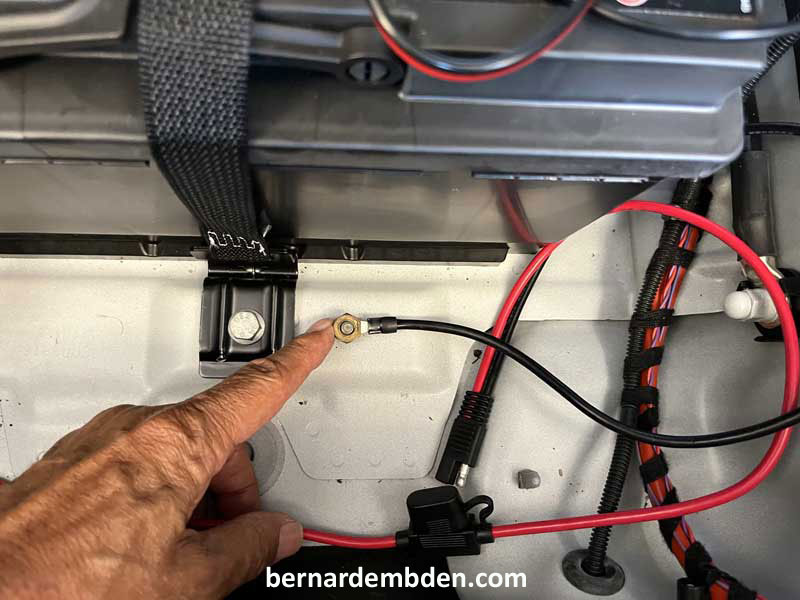
Connecting the positive and negative leads to the battery was always going to be a challenge. I thought I had found a perfect spot for the ground connection (photograph below) I was wrong. (more on this later).
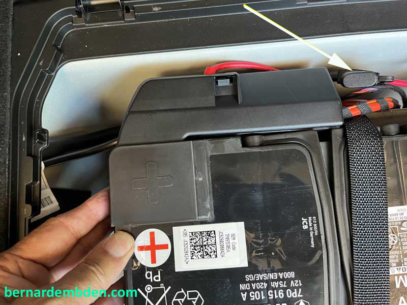
I removed the cover from the buss bar (positive side of the battery) and attached the positive wire for the battery maintainer.
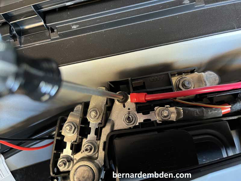
The buss bar cover had to be massaged slightly to fit over the attached wire.(green arrow photograph below)
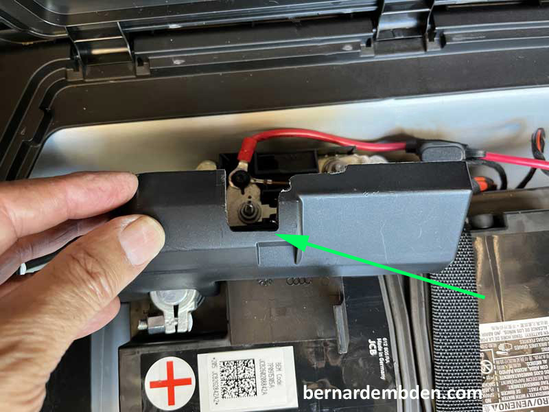
This is important. For this configuration a fuse is absolutely necessary between the battery and the connection port. Fuse must be located as close to the battery as possible. This protects the circuit in the case of a rear end collision that could introduce a short at the connection port.
Note inline 15 AMP fuse in positive connection. (white arrow photograph below)
Sealing the two inch opening in the battery compartment to prevent water ingress is pretty damm important.
In addition you need enough wire and connections to attach to the battery, through the sealing plug and to the connection portal installed at the diffuser. Purchasing a longer wire with pre-made connections will not work unless you intend to seal the opening with a massive amount of silicone caulk.
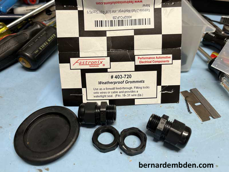
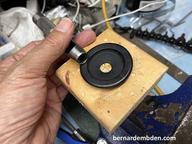
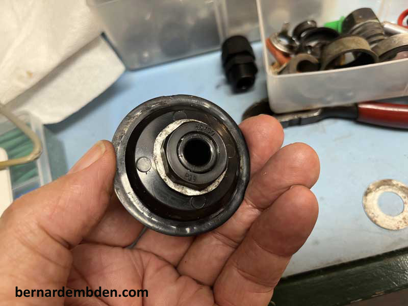
There is a better way. I purchased a weatherproof Grommet set (403-720) and started with a two inch rubber plug. (You did retain the original plug if you were careful enough not to push it in while trying to remove it). Using a gasket maker hole punch I punched a half inch hole in the rubber plug, pushed the weatherproof grommet through the hole, attached a thin washer and screwed the nut on. (photographs below)
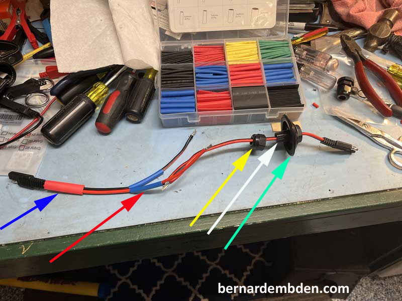
Before soldering, feed the wires through the weatherproof connection making sure to follow the sequence in the photograph below.
Blue arrow. Large heat shrink tubing covering both wires.
Red arrow-Heat shrink tubing on individual wires.
Yellow arrow-Compression nut for weatherproof connector.
White arrow-Front of weatherproof connector. (this will be inside the battery compartment).
Green arrow-Two inch rubber plug. (Orient plug so that it installs from inside the battery compartment.
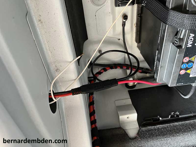
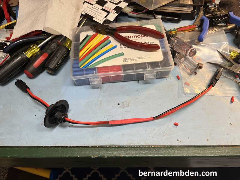
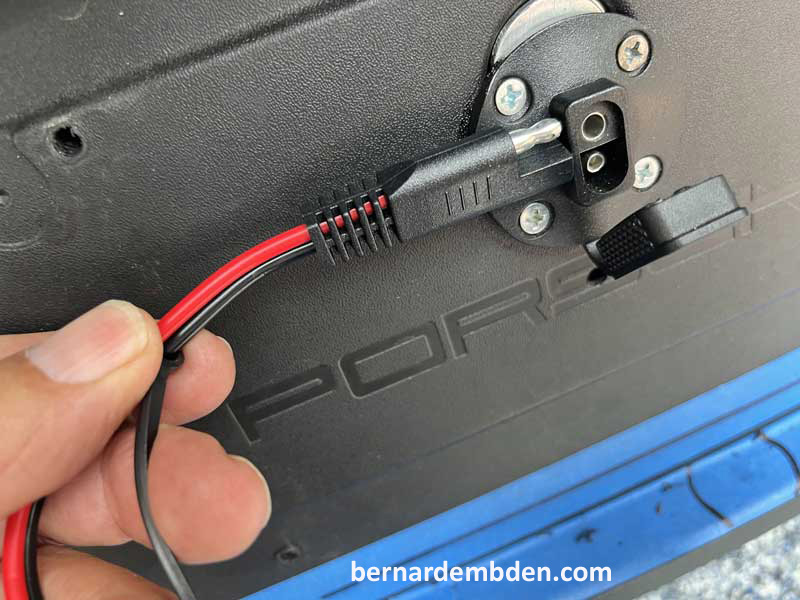
Finished union between the battery and diffuser port. Note: I had to reverse the wire colors to maintain polarity
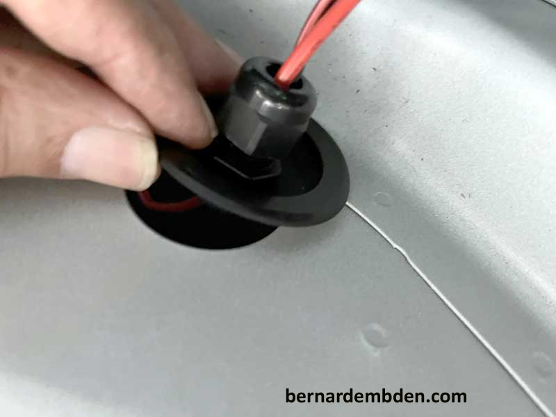
Connect wire loom union (above photograph) to battery and connection port connectors making sure to push extra wire (slack) including the connection plug, into area between diffuser and battery compartment. Tighten compression nut. Tie wrap wire union to existing wire loom and install rubber plug to opening in battery compartment. (photographs below)
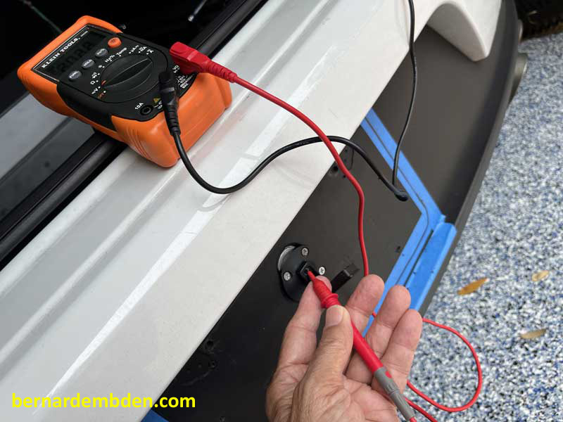
This is important.The connection to the battery consists of four different wire connection plugs and a soldered connection. Test access port connection for polarity with battery maintainer wire cable. Positive (red) in on the top (female connection) of the port terminal. Using a meter test top connection to positive side of battery. don’t screw thus up. (photographs below)
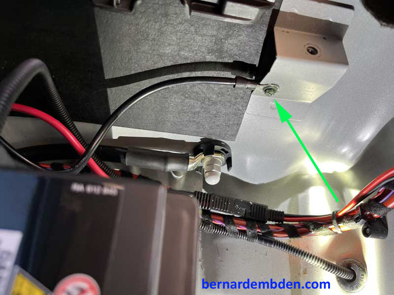
Reinstalling the sub-woofer I discovered that the ground connection I used was a problem.(noted earlier) The screw end locates in a slot in the bottom of the sub-woofer, thus my ground connection prevented the subwoofer from seating. Fix was to move the ground connection to a hole drilled and tapped on the side of the bracket that secures the subwoofer. (green arrow photograph below)
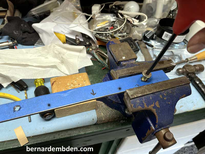
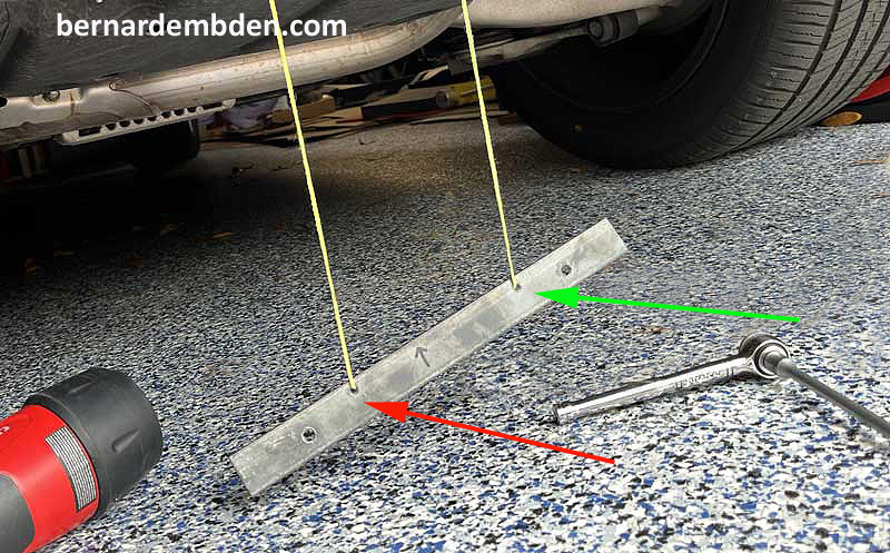
Photographs below. Using a length of tape, mark the locations of the mounting holes for the tilt plate holder and transfer them to a length of 1/8 by 1 inch metal stock available at Home Depot or Lowes. (green arrows second photograph below). In addition two small holes were drilled and tapped between the larger holes, in the top half of the metal stock. (yellow arrows).
![]()
Drill and tap the metal stock to accept flat head screws robust enough to hold the tilt plate assembly. Drill and tap the two smaller holes to accept two machined screws. (yellow arrows photograph above) Cut the metal approx. 2 inches from each tapped larger screw hole.
Offer up the drilled and tapped metal stock to the license plate attachment holes. You will notice that there is a slight bend in the diffuser. Duplicate this bend on the metal stock so it conforms to the bend of the diffuser.
With the metal stock conforming to the diffusers contour, and the two mounting holes lined up, (white arrows) drill through the two small holes at the top into the metal stock. (yellow arrows). Make sure the larger holes in the diffuser are big enough to accept the attachment screws. (white arrows)
Remove two screws that hold the bottom of the diffuser. Note: The objective was always to get the license plate reinforcement metal bar behind the diffuser without actually removing the diffuser or bumper.
Using a snake, coat hanger wire or copper lashing wire, snake from the two small holes in the diffuser to exit between the bottom of the diffuser and the diffuser mounting points. By removing the two attachment screws (above photograph) you will now have enough room.
Carefully examine the two photographs below.
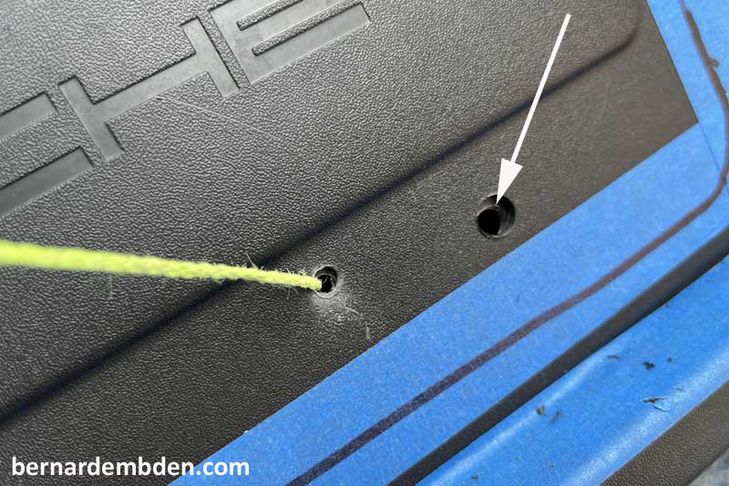
One unbroken piece of string enters the right small hole in the diffuser, (white arrow first photograph) exits at the lower edge of the diffuser. It continues through the front of the corresponding small hole of the metal stock (green arrow second photograph).
The string then goes behind the metal stock and re-enters, from behind, the second small hole (red arrow second photograph).
From there it continues up behind the diffuser to exit from the left small hole in the diffuser (yellow arrow).
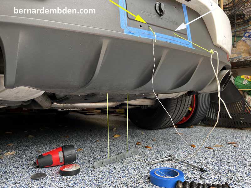
By pulling both ends of the string simultaneously, the metal stock is drawn up through the rear of the diffuser attachment (screws removed prior) and up flush behind the license plate attachment points.
By holding the string ends taunt, the metal stock tapped screw hole can be seen behind the diffuser. (white arrow photograph below)
This allows the two larger screws to be installed and temporarily tightened.(white arrows) While the large screws hold the metal stock in place, the string can be removed and the two small screws can now be installed. (yellow arrow photograph below). These small screws serves two purposes.
It allows the installation of the metal plate via the string pull method.
Once the screws are installed, it secures the metal plate to the diffuser, thus allowing the larger screws to be removed necessary to install the tilt license plate holder.
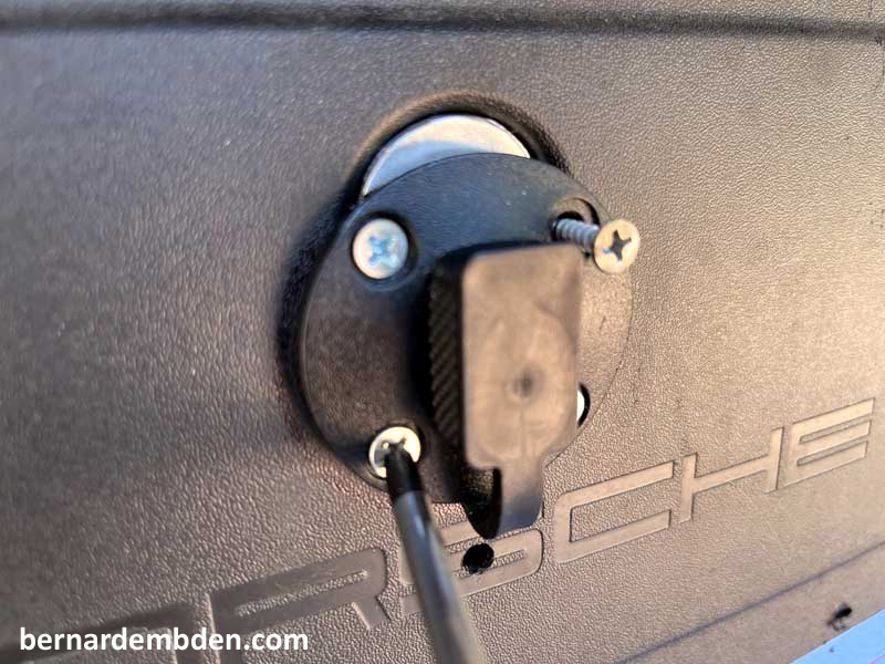
Based on testing on some scrap wood I knew I would need 1/2 inch standoffs. Ideally I wanted to install them utilizing the existing license plate attachment holes (green arrow photograph below). That location proved not ideal. It would bump against the nuts holding the license plate, moving the top of the tilt holder too far out. Moving the location out and down provided the result that I wanted.
Reinstall two screws that secure lower diffuse panel. Offer up tilt license plate holder and install the two mounting screws. Note only one torsion spring is installed.

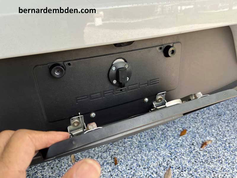
Project complete
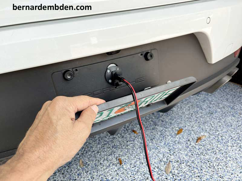
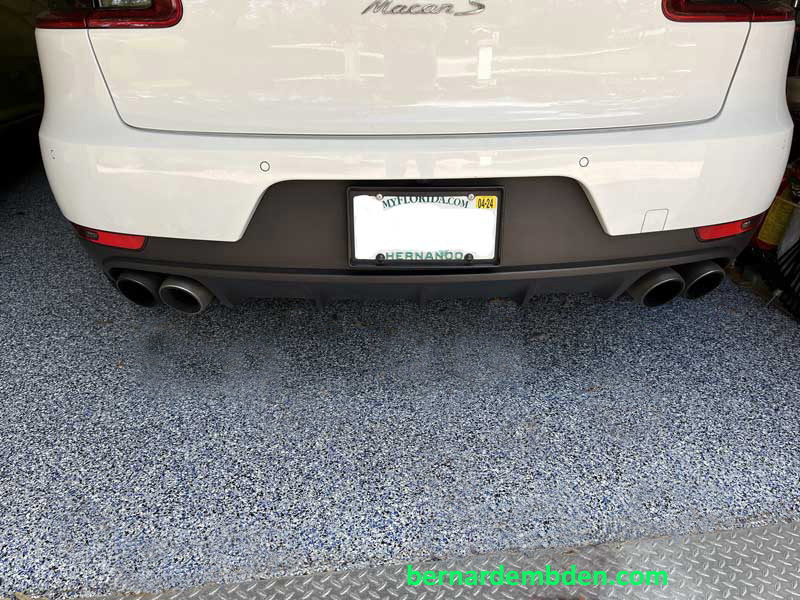
Drive Safe.
