
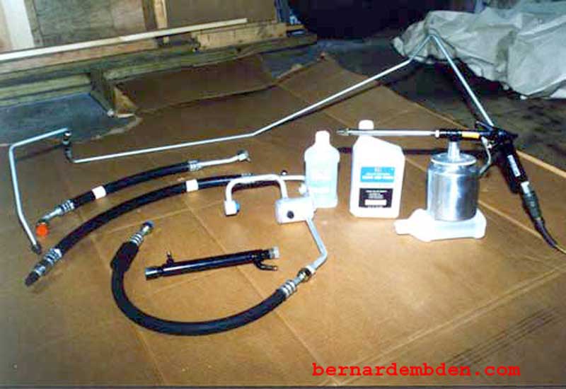
Once the A/C stopped working on my 1978 Jaguar XJ-S, I decided to completely overhaul the air conditioning system. This project would involve completely flushing the system, then replacing the expansion valve, the compressor, the receiver/drier and all the hoses and "O" rings. The fact that A/C hoses were no longer available for the Pre-HE XJ-S meant that I would either have to:
1) Remove the old fittings and have the hoses replaced.
2) Do the rebuild with A/C components from the 1988 XJ-S model. (This would require using the 1988 fuel cooler as well).
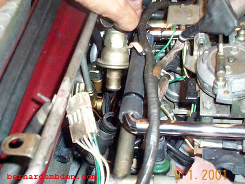
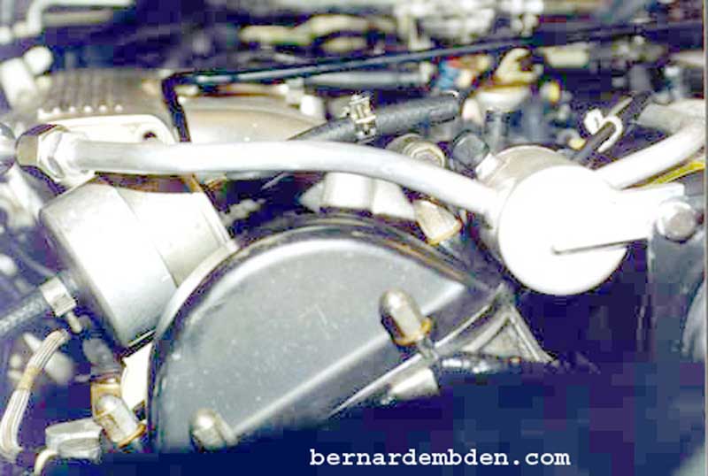
First, depressurize the A/C system (Freon should be recovered by a professional A/C shop) and remove the air pump valve (above photograph).
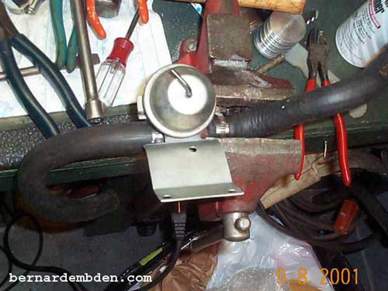
Remove the water heater valve from the firewall. Once this valve is removed, modify as per above photograph. This will allow you to access the hose clamps and remove the hoses from the valve without removing the valve from the firewall. Remove the right side air injection rail. This will allow you to replace the low side hose. Remove A/C compressor and hoses. Plug all A/C openings. Be careful removing the hose and pipe from the expansion valve, and removing the expansion valve from the evaporator. Make sure you use the appropriate size spanner to back all connections to the expansion valve and the evaporator. Breaking the evaporator leaves you with two options:
(a) Life long therapy (b) Junk the car.
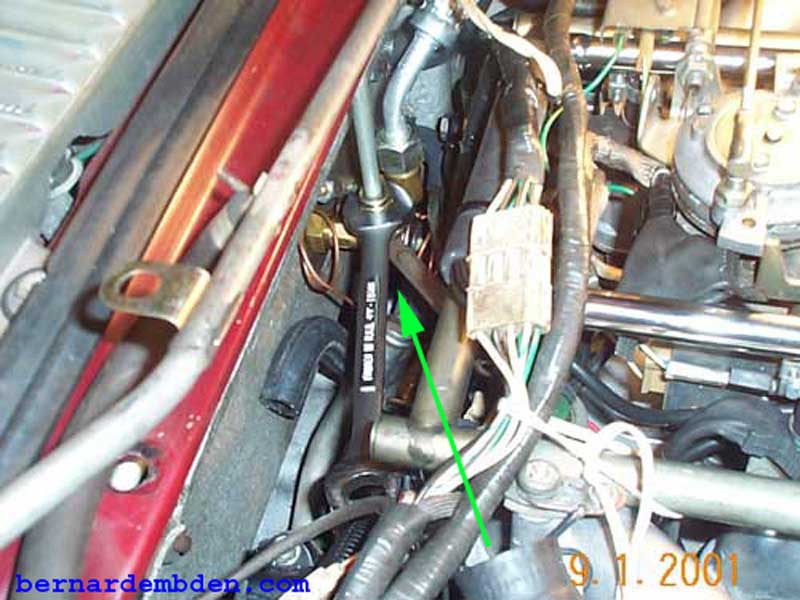
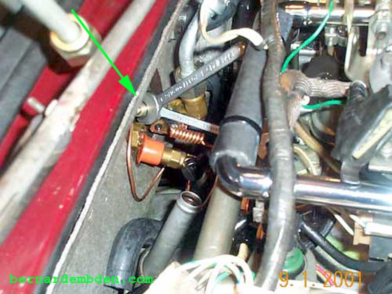
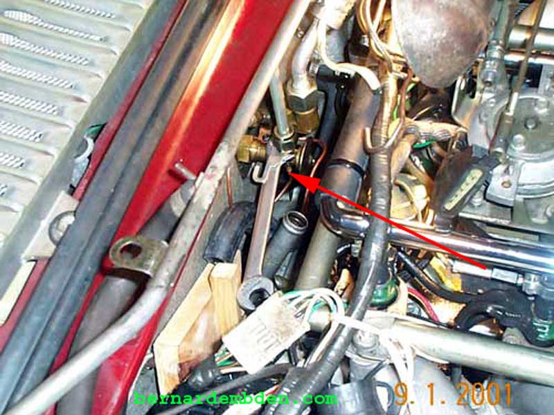
Above photograph shows the high side A/C pipe being removed from the expansion valve. Note the two spanners to back the valve connection. (green arrow)
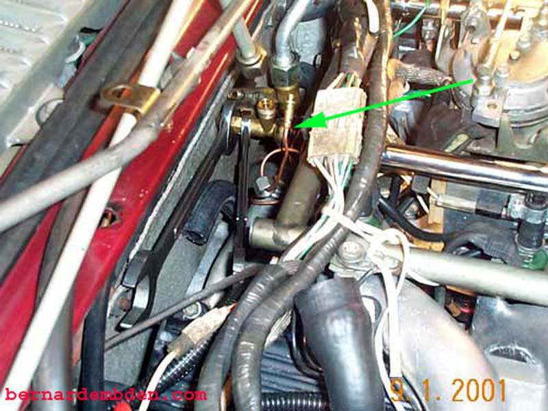
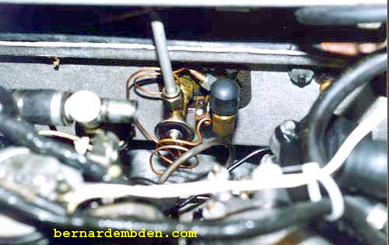
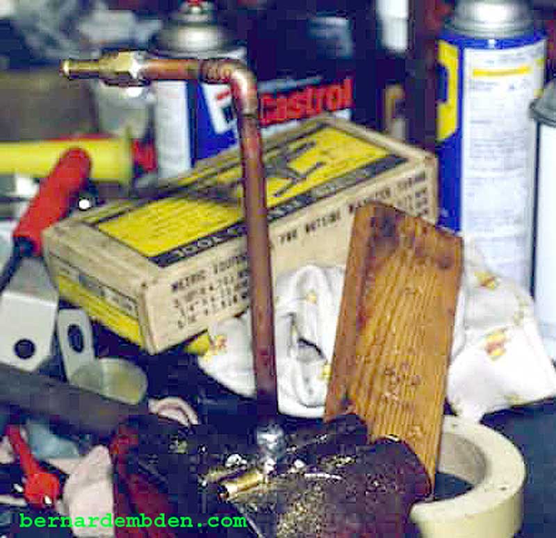
The above photograph shows the removal/installation of the new expansion valve's capillary tube. The same method is used to remove and install this capillary tube.
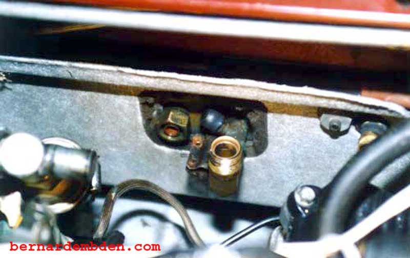
Pictured above is the evaporator connections with the expansion valve and low-pressure hose removed. While you have access to this location, examine the hoses to the heater core carefully. If they show any sign of deterioration or if they are more than five years old, Replace them now. Getting the hoses off, especially the lower hose, is a real PIA. Use a sharp razor to slit the hoses before pulling then off.
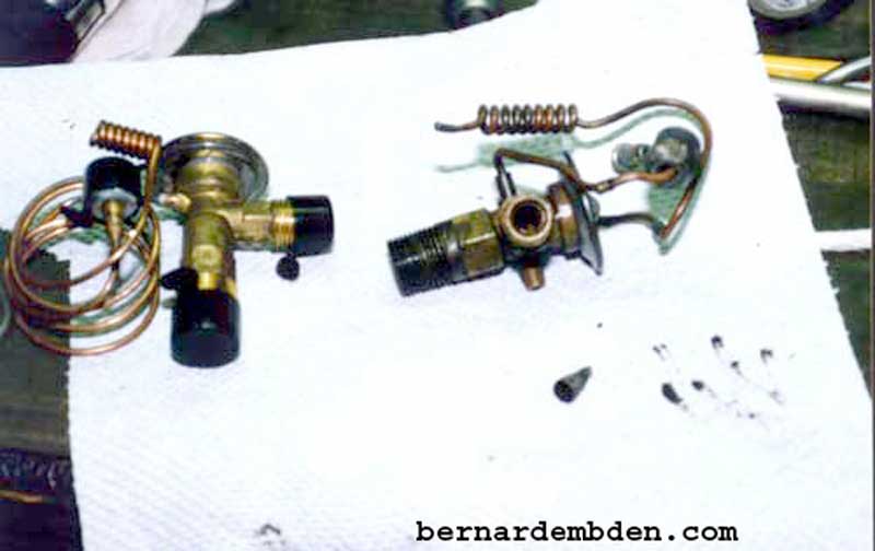
Pictured above are the old and new expansion valves. Note the clogged up expansion valve inlet screen (some of the crap I removed is visible on the right). In an emergency, this screen can be cleaned and reused. Make sure you try to duplicate the way the copper tubing sensors are oriented. This will greatly facilitate installation of the new expansion valve. The curled up copper tubing mount to the exit pipe of the evaporator. Its function is to monitor the evaporator outlet temperature and adjust the Freon flow accordingly.
There is a slight difference in calibration between the R12 and R134 expansion valves. The difference is minor, not enough to change a properly working valve. If, however, while converting to R134, the expansion valve is changed, then use an expansion valve designed for R134.
The above photograph shows the new expansion valve installed. Be careful in bending the small copper tubes as they bolt to the low side of the evaporator. Make sure that the high-pressure pipe is lined up, "O" ring seated and hand tight in the expansion valve before permanently tightening the valve connections.
It seems that an unfortunate by-product of purchasing non-Jaguar parts is that some parts will be out of specs. If you are willing to pay dealer prices, further modifications are probably unnecessary. Because I have an aversion to spending money, especially my own, I bought the A/C parts from an independent Jaguar reseller. Because resellers all get their parts from basically the same source, be prepared for the following:
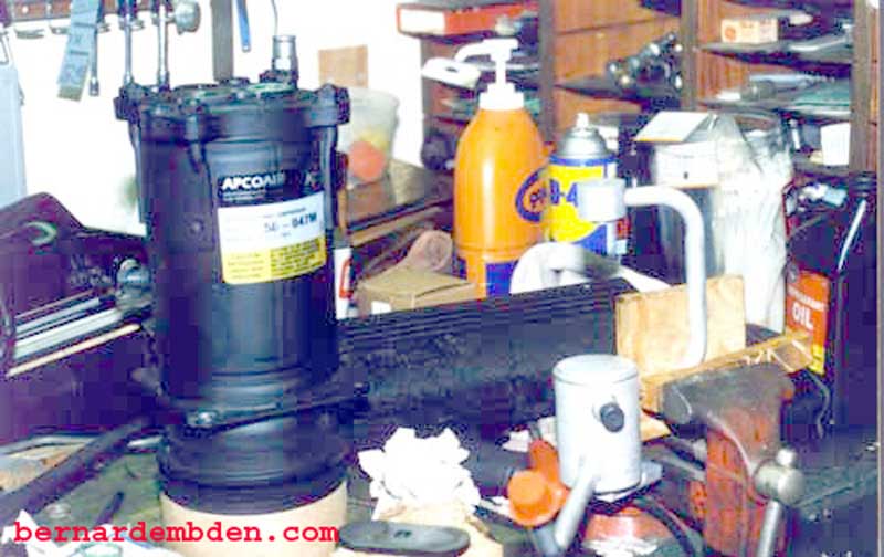
The high side A/C muffler pipe was at least 1/4 inch off the correct location at the back of the compressor. In addition, the muffler bracket was an inch away from its mounting location on the flange of the compressor. (more on this later). The above picture shows the muffler pipe mounted in a vice. Note how the pipe is protected. Be careful not to put any strain on the weld connections. I used the appropriate size tube bender to twist the pipe until it lined up correctly.
Once the high and low-pressure hoses were prefitted to the compressor, further modification of the muffler pipe became necessary. The straight pipe was in danger of contacting the hood and had to be bent over the cam cover. In addition, a spacer or shim had to be fabricated to bolt the muffler bracket to the compressor flange. I was also not comfortable with the unsupported low-pressure fitting. I decided to fabricate a bracket to support that fitting as well. The new/rebuilt compressor comes with "O" rings installed at the rear outlets. Do not use these "O" rings if they have been compressed. Once compressed, "O" rings should be discarded. I purchased my "O" rings, as well as most of the hardware for this project from Coventry West. (http://www.coventrywest.com/). If you are unable to get the correct "O" rings, bite the bullet and buy "O" rings from the Chevrolet dealer. They sell a revised "O" ring package for the A-6 compressor, part number 272-4674, for about $10.00 US. I know, I know. Its highway robbery. My personal experience has not been good with these revised thinner "O" rings, I prefer to use the thicker original "O" rings.
Note: The rear compressor "O" ring installation is covered in great detail in another link in this website.
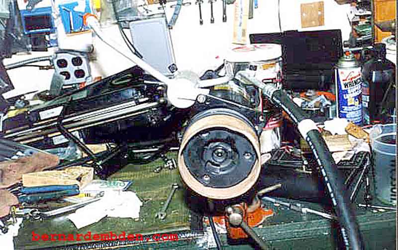
Gently bend the muffler pipe as shown. If necessary support weld connection in a vice. Modify and pre-fit all compressor connections before installing "O" rings.
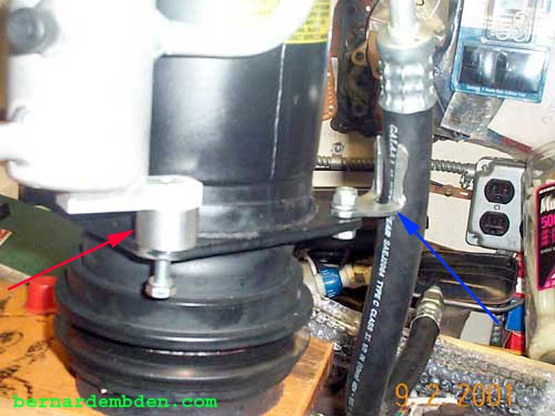
As noted prior, high-pressure muffler pipe bracket is inexplicably one inch too short. I shimmed the space by cutting an exact length spacer from aluminum stock. (red arrow above photograph) I was not happy with the unsupported low side hose, so I fabricated a bracket to support that as well. (blue arrow)
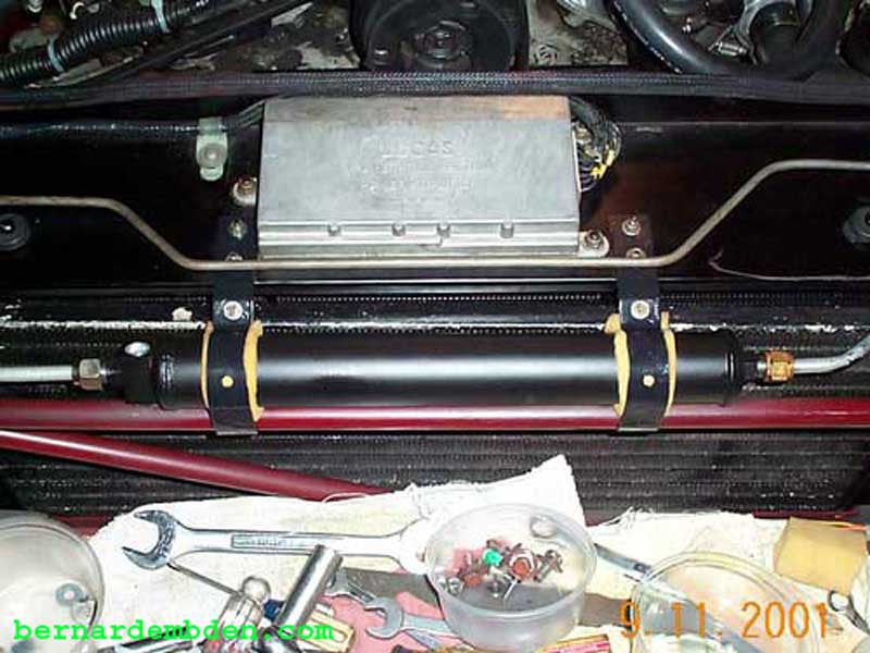
The new fuel cooler required re-routing of the fuel return lines. Not wanting fuel hoses scattered about the engine, I fabricated this fuel return pipe to connect the fuel cooler to the fuel pressure regulator.
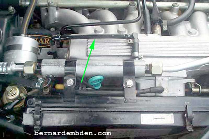
Fuel cooler and fabricated fuel return pipe installed. (green arrow photograph above) Note brackets on the air cleaner to accept the new fuel cooler. These brackets may not be on some Pre-HE's. If necessary, fabricate new brackets. The fuel flows from the fuel rail, through the fuel cooler and back to the single pressure regulator. From the regulator the fuel returns to the fuel tank.
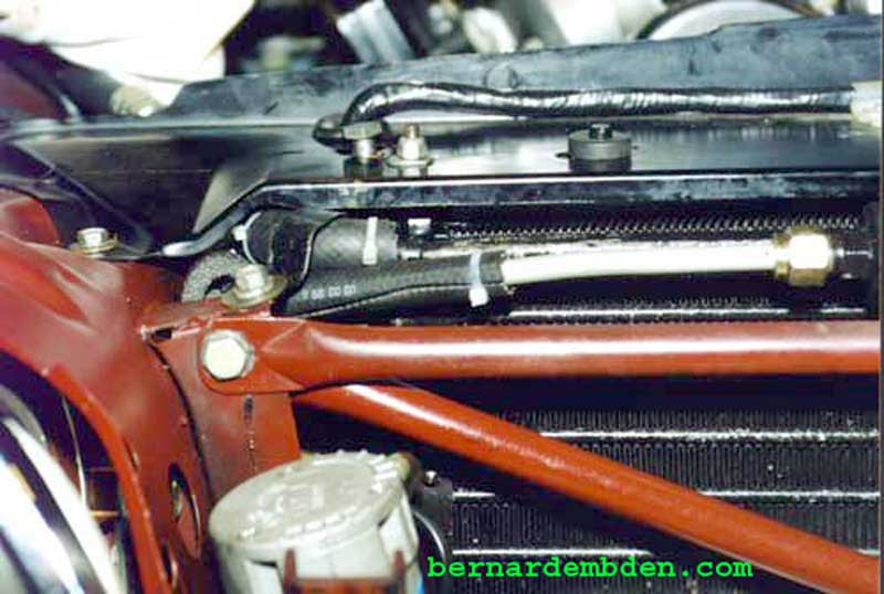
To prevent the possibility of chafing against the radiator top rail and or the condenser bracket, the pipes going into the condenser and receiver/drier were covered with split heater hoses. Note the reworked condenser-mounting bracket. I permanently removed it from the radiator support to facilitate repeat removal of the radiator.
Installation of new drier required sponge padding to attach brackets securely.
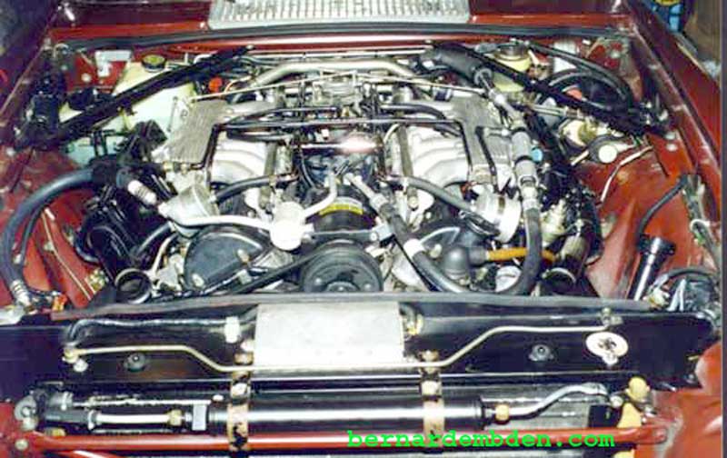
Air-conditioning upgrade and rebuild complete.
The photograph also shows the radiator bleed system on the Pre-HE's, along with my installation of a radiator coolant recovery system.
Note: Cleaning and flushing, along with charging the system with R134 is covered on a separate link.
