
Replacing the anemic original Jaguar alternator with a modern Unit.
The original 65-amp unit might have been state of the art 26 years ago, however it was challenged just to maintain 12 volts at idle with the lights and A/C on. While there are a number of alternators that will physically fit in the air pump location, I decided to relocate the alternator to the air pump location and replace it with a Delco CS-130 alternator for the following reasons:
a) The unit closely matched the size of the air pump it was replacing.
b) The standard configuration was 105 Amp.
c) It was a self-exciting Unit.
d) It looked better that the CS-130D alternator.
d) It was readily available. GM made hundreds of thousands on these alternators from 1986 to 1996. The cost of a Delco CS-130 alternator at any US junkyard should be $10.00 to $15.00 US.
Some independent alternator rebuilders have expressed some concern that this unit suffered from overheating and had a somewhat high failure rate of the rear bearings. For me this was not an issue. When one considers the vast number of these alternators, the failure rate was well within the norm.
Alternator configurations generally can be classified in three main categories:
1) Self-exciting alternator. This unit uses a special voltage regulator that doesn't need an ignition wire to activate it. The voltage regulator contains circuitry that uses the residual magnetism in the alternators fields to decide when to turn the alternator on. The regulator does this by sensing the RPM the alternator is turning. Essentially, when the alternator gets to a pre-determined RPM, the voltage regulator turns it on. This unit has only one main large battery wire connected to it.
2) Two-wire alternator. In addition to the main battery wire, this regulator is activated by another separate wire. All self-exciting regulator alternators will work using the two-wire setup. In many ways this represents the standard alternator configuration.
3) Three-wire alternator. This is the most effective configuration. Essentially a closed loop "feedback" system. It uses a large battery wire, an ignition and or warning light connection and a voltage sensing wire. The advantages are a) the regulator is activated by the ignition/warning light wire, b) the sense wire, connected directly to the battery, continuously tells the voltage regulator the charge condition of the battery. (this information is significantly more accurate when sourced directly at the battery.) The voltage regulator infinitely varies the alternator output based on this information. No other configuration charges the battery as effectively. This is the configuration that I intended to use on this project.
Remove air pump, bracket and original alternator.
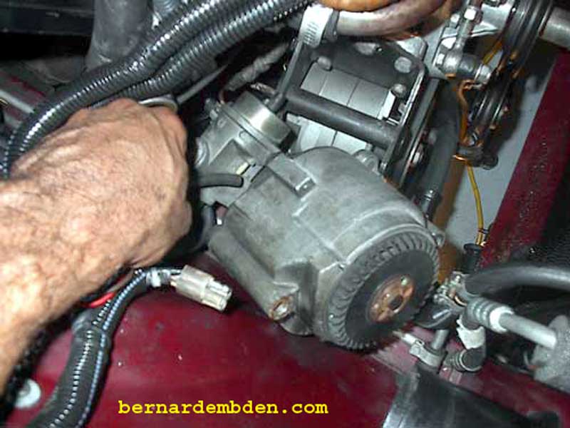
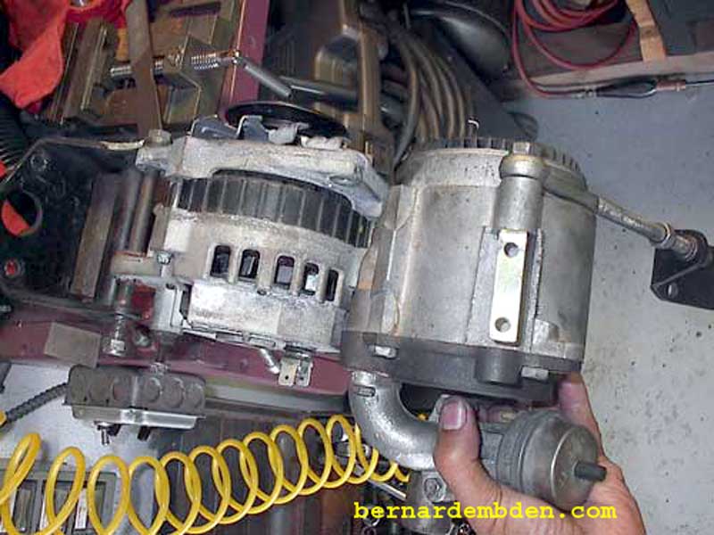
Comparison of the air pump and Delco CS-130 alternator indicates that they are almost identical in size, and most importantly, in the pulley and mounting locations. One other important factor has to be considered, the mounting and adjustment lug positions (clock position).
Most (not all) alternators are designed so the rear half can be assembled to the front half at different positions. This assembled position is referred to as the "clock" position. "Clock position" is used primarily in assembly to provide for proper exit of the wiring from the alternator, usually in any one of four directions, for use with different mounting setups. For this reason, clock position is always determined from the rear of the alternator with the threaded adjustment hole in the 12 o'clock position.
The original air pump's clock position was 6:00 (adjustment lug at 12 o'clock.) While the same mounting-lug clock position should work for the new alternator, I believed that, without the air pump's plumbing, I could move the alternator closer to the engine. This would shorten the belt and adjustment rod, and combined with installing an alternator with a clock position of 8.00. ( the adjustment-lug at 12 o'clock and the mounting-lug at 8 o'clock) would provide for neater engine "packaging").
Finally, note that mounting-lug clock positions cannot be changed, you must source the alternator with the mounting-lugs in the clock position you want. Clock positions also cannot be changed on alternators with mounting-lugs attached to the front and rear halves of the alternator.
For this project the alternator was sourced from a 1995 Pontiac Grand Am with a V-6 engine.
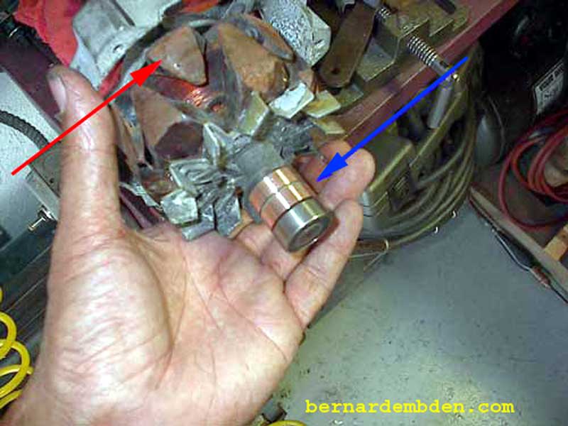
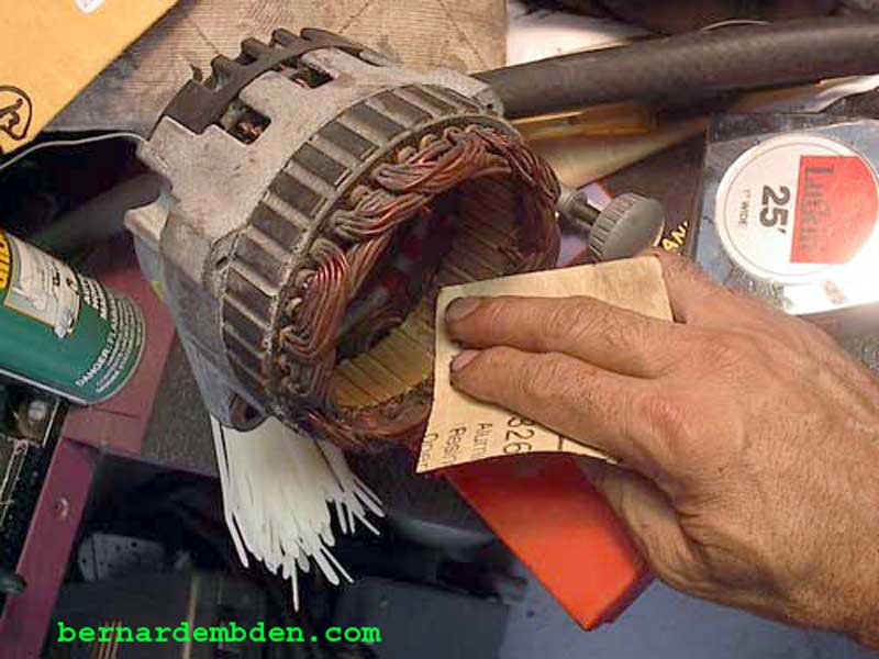
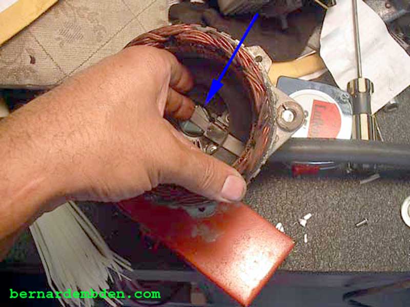
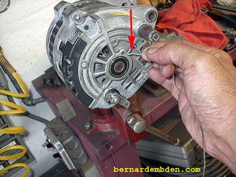
This is the time to check the alternator. Mark the casing of the alternator to determine front and rear orientation. This is the "Clock position" Disassemble the alternator. This alternator uses internal and external fans (internal rear fan in photo below). Check the drive end (front) and rear bearings for end play. Clean the brushes. Clean the slip rings by rotating the rotor while holding a polishing cloth against them. (blue arrow). Any alternator from the junkyard will have rust. Remove rust from the rotor (red arrow) and stator (bottom picture) with sandpaper. Use compressed air to blow out accumulated dust.
Push the springs and brushes (blue arrow) back into their receptacles and restrain with wire through the hole provided. This will retract the brushes during assembly.
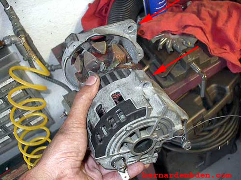
Install rear alternator case. Note the mounting lugs on the front and rear of the case (red arrows photograph below). This means that the clock position cannot be changed.
In the photograph below, the blue arrows indicate clock position marks. Red arrow identifies alternator brush retaining wire.
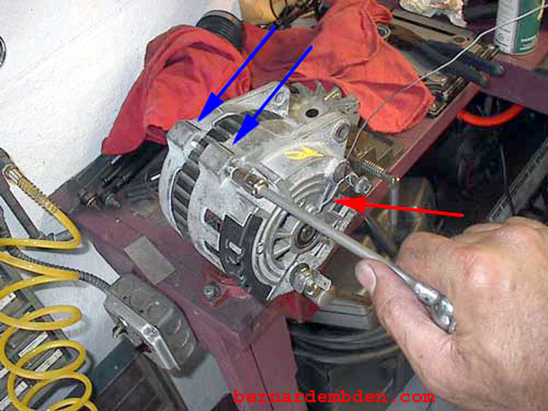
Simply pull wire out (red arrow) when the case is assembled. This releases the brushes allowing them to make contact with the slip rings.
The original alternator was designed to use a 15 series belt. This required a pulley with a 10mm wide "V". The belt that would be driving the alternator in its new location will be a 17 series belt, which requires a 13mm (1/2 inch) wide pulley "V". This is not a small problem. A too small pulley "V" will result in the belt riding too high in the pulley, an inability to turn the pulley properly along with shortened belt life.
Another problem was the diameter of the pulley. The original pulley diameter was 3 inches. Most pulleys are available in 2.5 inch diameters. I do not recommend this size pulley to be used with a 17 series (13mm wide) belt. The wider belt does not "wrap" around the pulley as effectively. My recommendation is at least a 3" diameter pulley.
You can get a "wide belt" pulley from a number of sources, however most are 2.5 inches in diameter. I was able to source a 3.25" wide belt pulley (1/2 inch) from Canton Racing Products. At $32.00 US, this billet aluminum pulley cost more that the alternator, but it does look good.
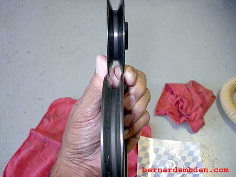
Photograph below compares the "V"'s of the air pump and Canton Racing pulleys.
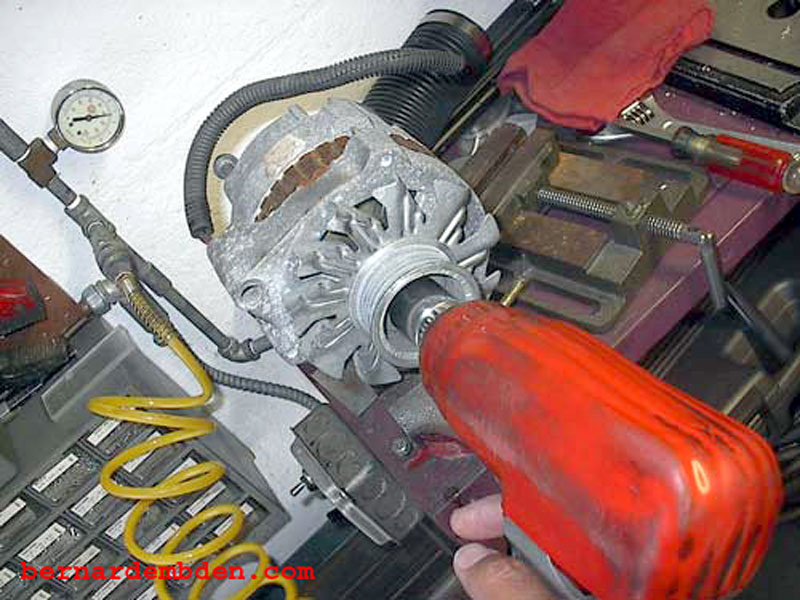
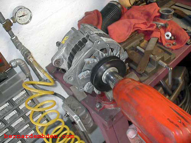
Remove the original pulley from the CS-130 alternator and install the new pulley. (photographs below) There is absolutely no substitute for an air tool for this job.
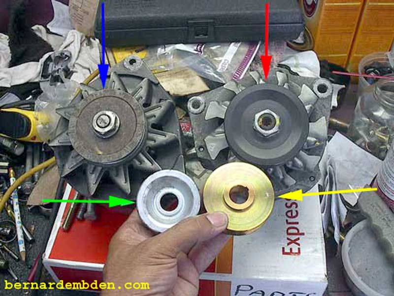
Comparison of the various pulley diameters are shown in the photograph below:
The original 3" pulley (blue arrow).
New 3.25" pulley (red arrow)
Original 1.5" serpentine pulley from the CS-130 alternator (green arrow)
New 2" pulley (yellow arrow).
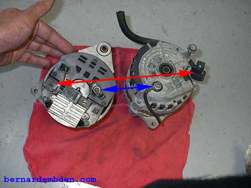
Photographed below are the rear of the original and replacement alternators. The red arrow shows the original charge indicator light connection and the unique plug on the replacement unit. This plug is specific to the CS-130 alternator. Make sure you get this plug when you acquire the alternator. This part can also be sourced from www.painlessperformance.com. The blue arrow shows the battery connection on both units.
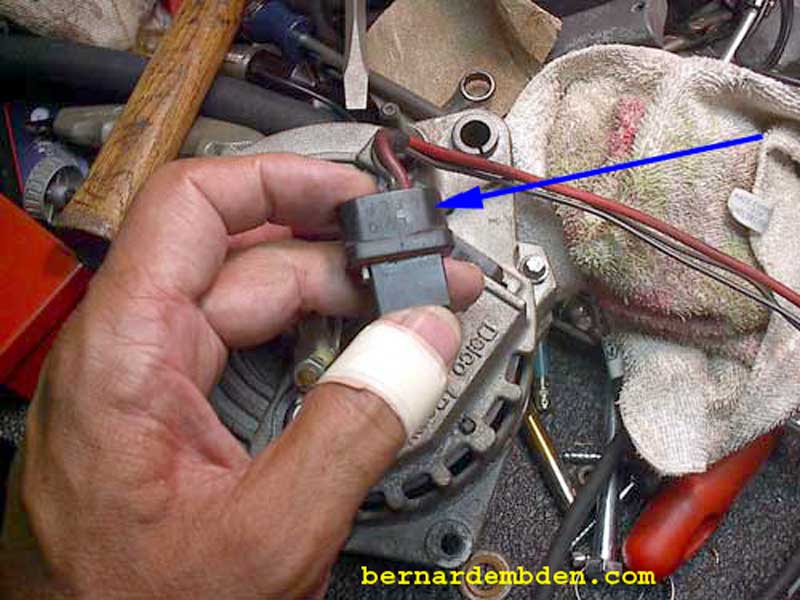
The CS-130 plug (photographed below blue arrow) identifies the individual wires by the following letters (S F L P) usually marked on the side of the plug:
(S) is the sense wire. This is connected directly to the battery, or in the case of the Jaguar XJ-S, to the bus bar.
(F) is connected internally to field positive and can be used as a fault indicator.
(L) is connected to a charge indicator light, or to a resistor, or to both.
(P) is connected to the stator and can be connected externally to a tachometer or other device.
The two that are important are the S and L connections.
This model alternator was used on virtually all GM vehicles for more than a decade. Depending on the vehicle it was designed for, some fabrication will be required in mounting the alternator. Remove the air pump bracket and secure in a vise to determine mounting methodologies. This particular alternator needed a spacer between the mounting-lugs.
![]()
A 3/8 galvanized pipe fitting was sourced from Home Depot and cut to length.
![]()
Cut pipe fits between mounting-lugs (blue arrow). A nut was used as a small spacer between the lug and air pump bracket (red arrow).
![]()
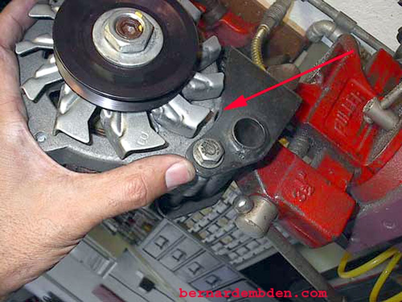
Now is the time to determine any clearance issues. Rotating the alternator all the way forward revealed some interference between the external fan and the air pump bracket. I used a grinding wheel to remove just enough of the bracket to allow the fan to clear. (red arrow)
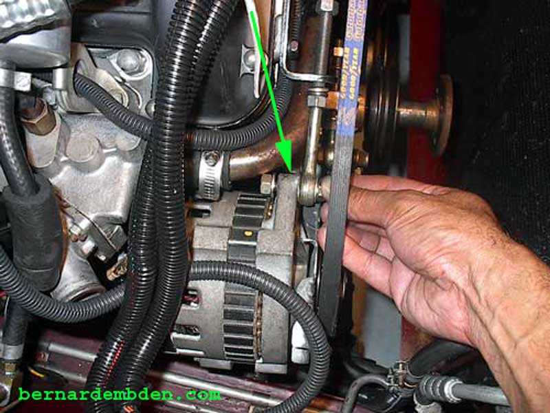
Preliminary installation of the alternator revealed two problems. The original belt was too long. Not a problem. Goodyear belt number 17581 was exactly what I needed. It was approx. 2 inches shorter than the original belt. (See photo below)
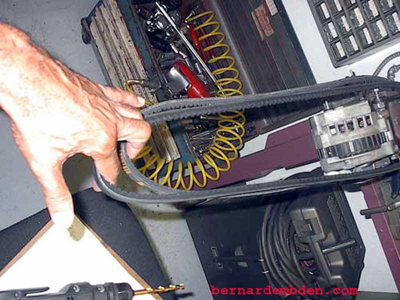
The second problem was more challenging. The alternator pulley diameter is 3.25 inches. The original air pump pulley diameter was 5 inches. By changing the diameter of the pulley I had also changed the angle of the belt from the crankshaft pulley to the new alternator. This resulted in the belt being approx. one inch higher and rubbing the fan jockey adjuster (red arrow).
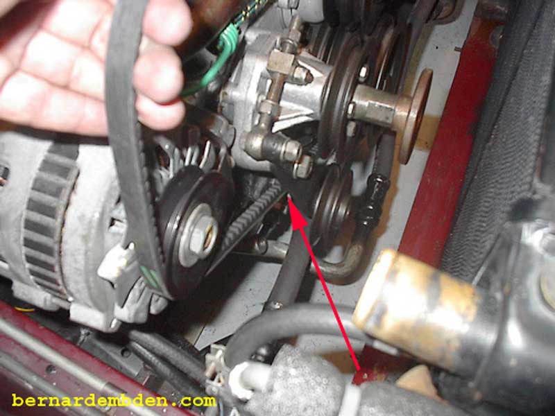
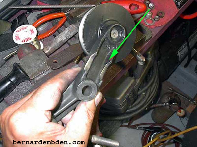
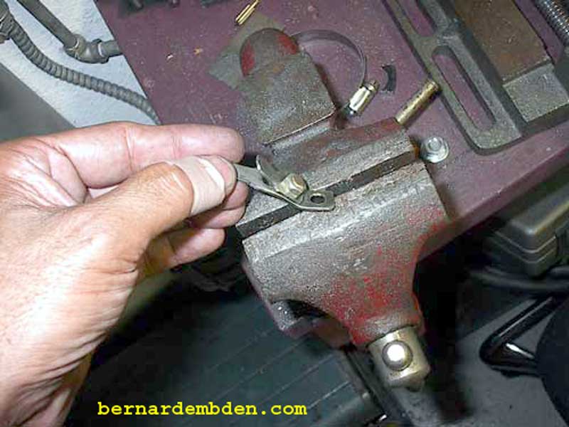
I explored a number of solutions. Lowering the air pump bracket meant that the alternator's adjusting rod would not line up properly with its bracket. Relocating the bracket was not a viable option, it would require fabrication of a complex mounting plate that would not look original. Examination of the fan jockey adjuster revealed that it could be modified. This adjuster is responsible for a small belt that turns the mechanical fan and uses only one bolt as the adjustment rod anchor. The adjuster arm however, is obviously over-engineered for its purpose, with a strengthening double ridge along the outer edges. These were the "ridges" that were interfering with the belt. Using a grinding wheel, I removed the ridges from the adjuster arm to provide enough clearance for the belt. (green arrows photographs below).
![]()
Cut and solder the alternator charge indicator wire to the "L" connection on the alternator plug.
Using 8 gauge wires lengthen the "S" (sense) connection from the plug (green arrow) and connect it to the bus bar. (blue arrow)
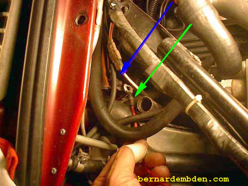
The original "U" shaped alternator battery connector would not clear the thermostat housing, so I fabricated a substitute from metal stock.
Connect the two existing battery wire connections to the custom connection (green arrow). Install plug (blue arrow). Heat shrink all connections and enclosed all wiring in heat resistant looms. This must not only work, it must look good. (photograph below)
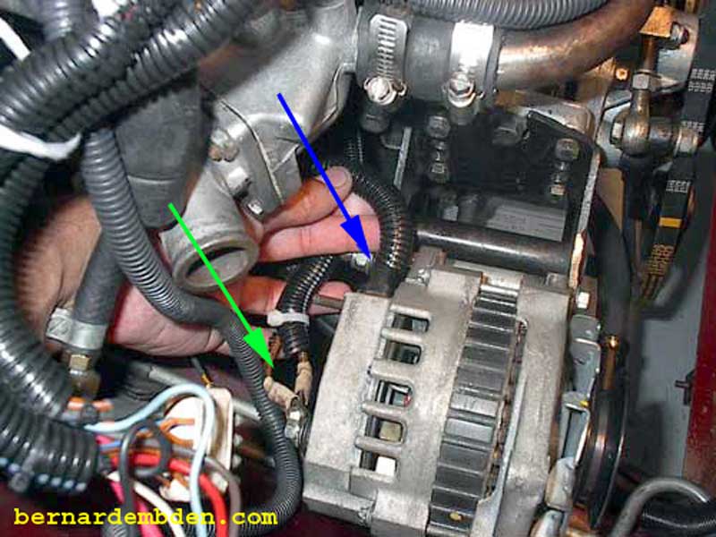
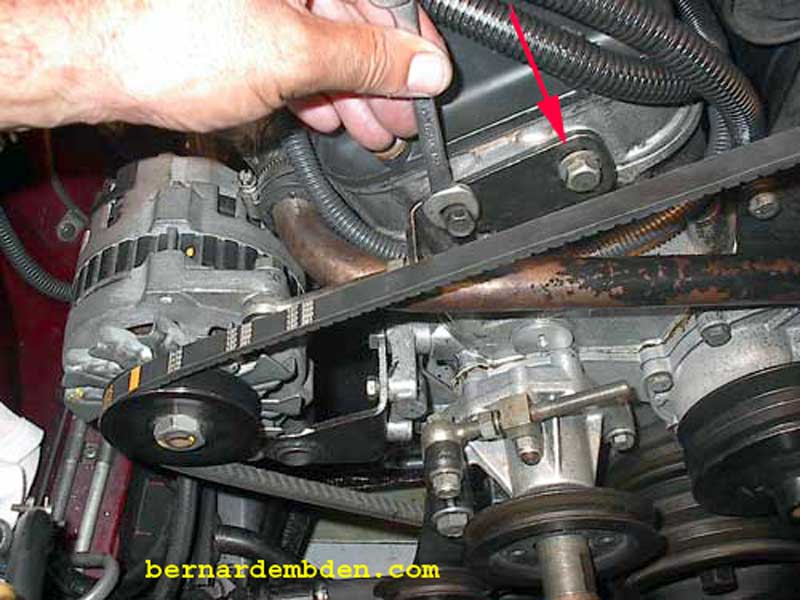
I used the adjusting rod from the alternator. It is shorter than the air pump rod and looks better. This adjusting rod lug connection was wider that the air pump adjustment rod. Grind down as necessary to clear the belt. The alternator top lug (green arrow photograph below) was not threaded so a bolt and nut was necessary.
The rear mounting hole in the adjustment bracket was modified. By cutting a slot it (red arrow) I was able to rotate the bracket so it lined up in a straight line with the adjustment rod.
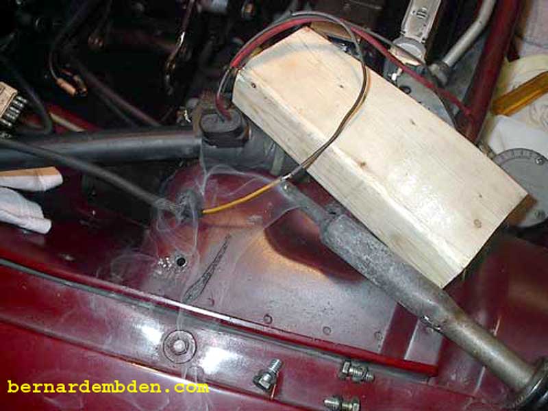
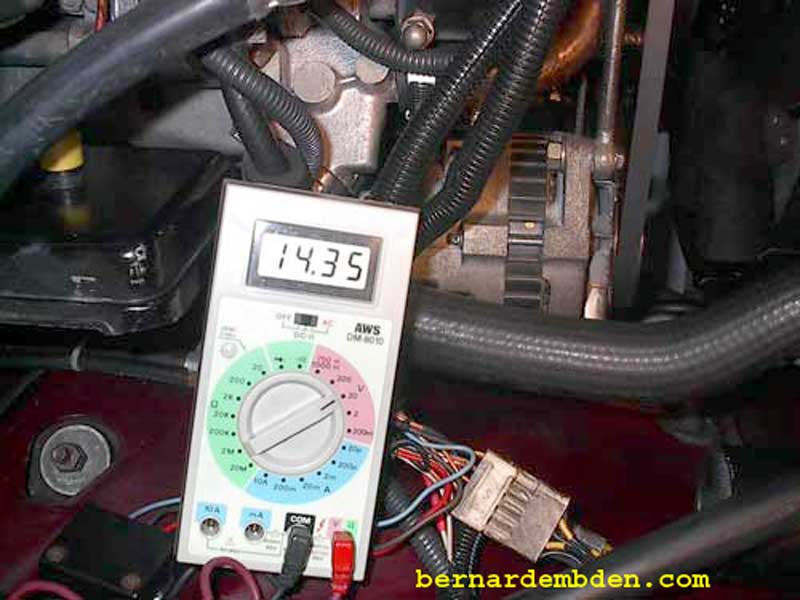
Don't be fooled by this picture. The shutter speed of the camera freezes the alternator fan. The engine is actually idling at 800 RPM with a dead solid 14.3 volts at the bus bar.
Project complete. Note perfect alignment of bracket and adjustor rod.
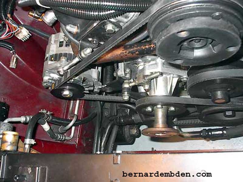

While not a difficult project it's important to get the details right. If done properly the alternator will look as if it belongs at this location.
