
Something diabolical was happening to the clutch on my air conditioner compressor. It would not disengage. The AC compressor continued to turn even after I pulled the 12-volt supply wire to the unit. It seemed possessed!
The AC compressor exhibited no unusual symptoms that would explain the locked clutch, there was no bearing failure, no unusual noise, no smoke, no fire.
On the contrary, the AC continued to work properly. The Jaguar cooled as good or better than the other cars I currently own, all of which have original factory 134a AC systems.
The 1978 Jaguar XJ-S uses the GM A6 compressor, a fairly common compressor used by a variety of General Motor's cars in the US. Based on the resellers I contacted, I was advised not to change the AC clutch. I difficult job I was told. Best left to the professionals. In addition, a rebuilt compressor was, in some cases, cheaper than a new clutch assembly, and darn close to the price of a rebuilt clutch.
I was not about to disassemble a perfectly working AC system because of a defective clutch. I sourced a rebuilt clutch assembly from Born-Again Air Corporation, in Midlothian Texas. (Cost, $68.00 US).
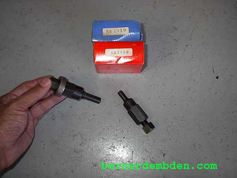
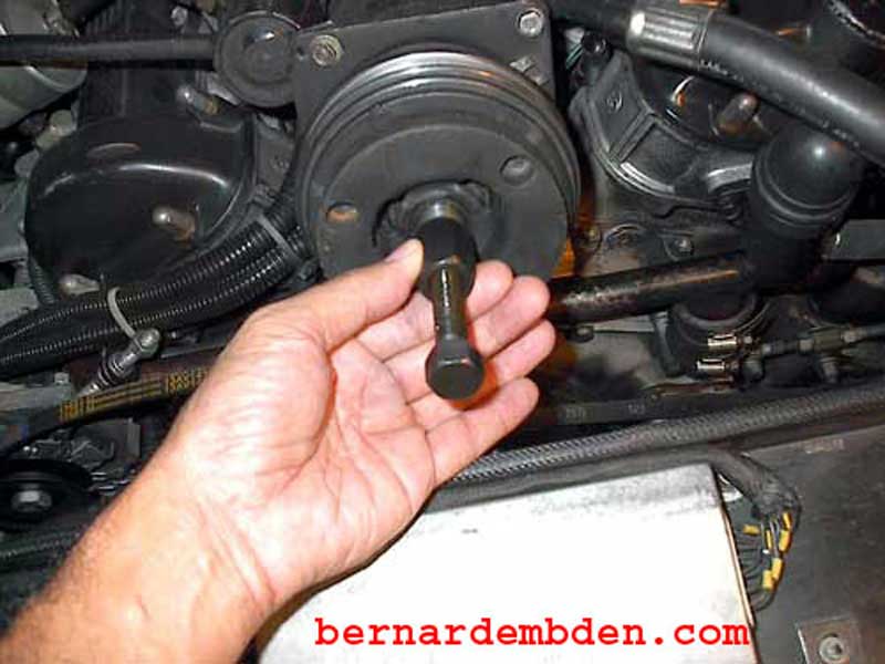
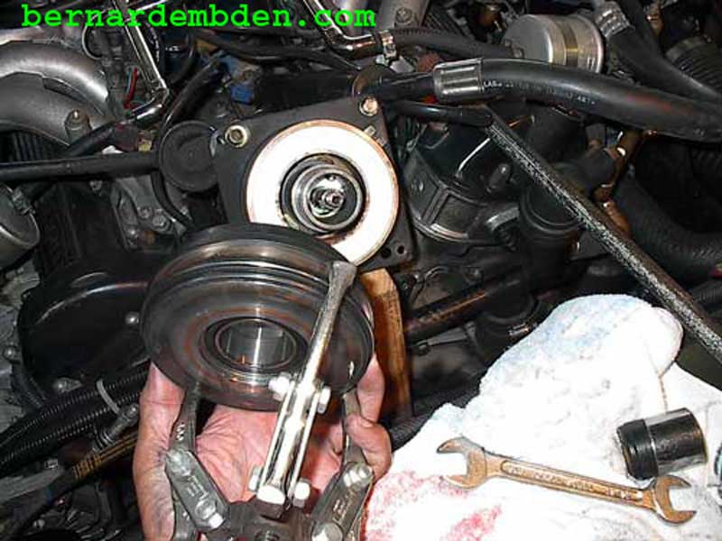
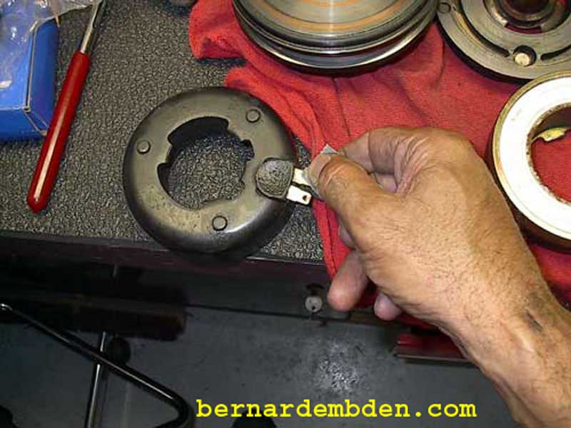
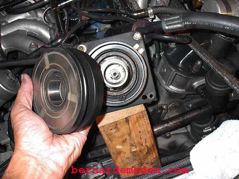
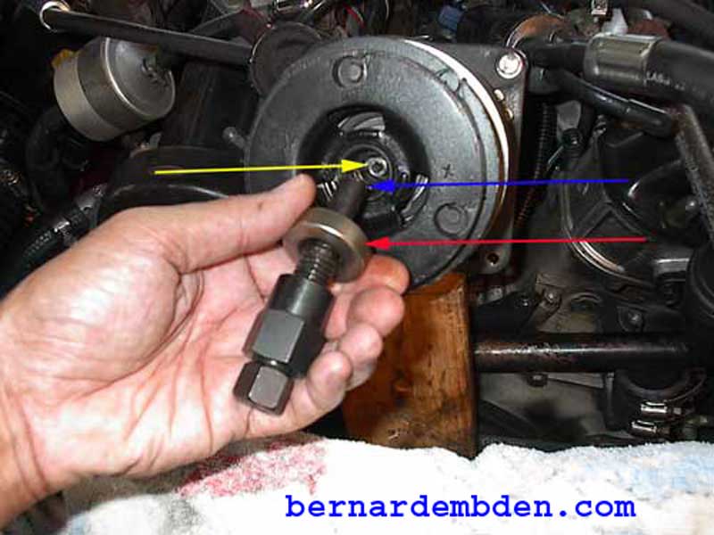
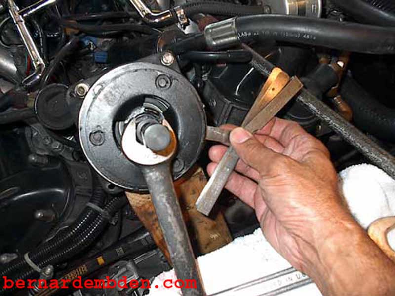
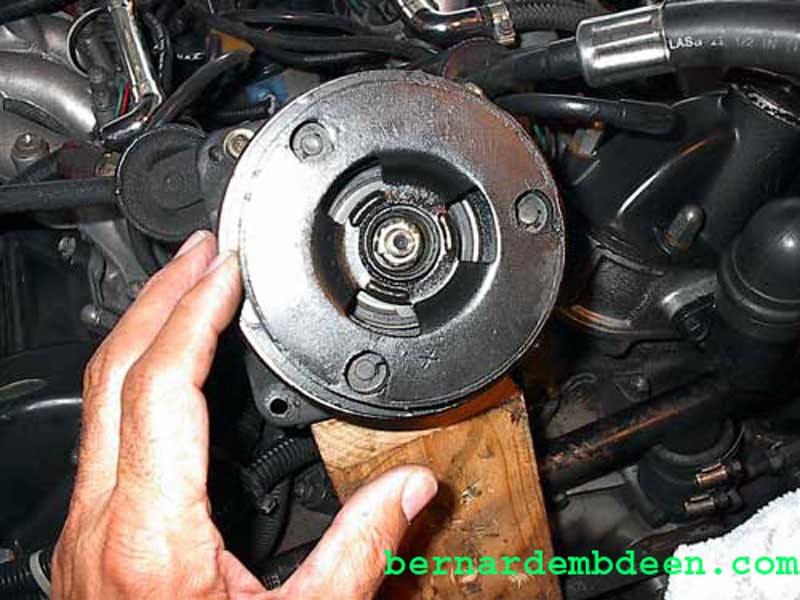
Photographed below are the clutch installer (in hand) and clutch puller. You will need both these tools.
Don't even think about starting this project without them.
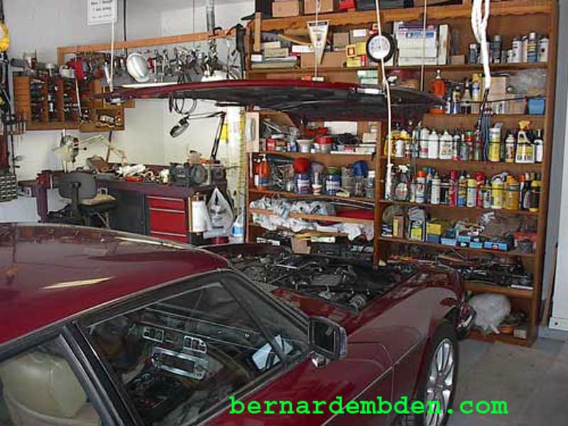
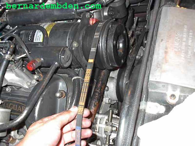
The project starts by removing the hood. Clearance in the Jaguar V-12 engine bay is non-existent. In addition, the AC compressor is located 3 inches from the radiator top support. While theoretically it is possible to do this with the hood on you will regret it. With my custom hood removal pulley system (see Hood Hoist System link on this website) the hood was off in 10 minutes. Another advantage of this system is that the hood stays suspended, out of the way.
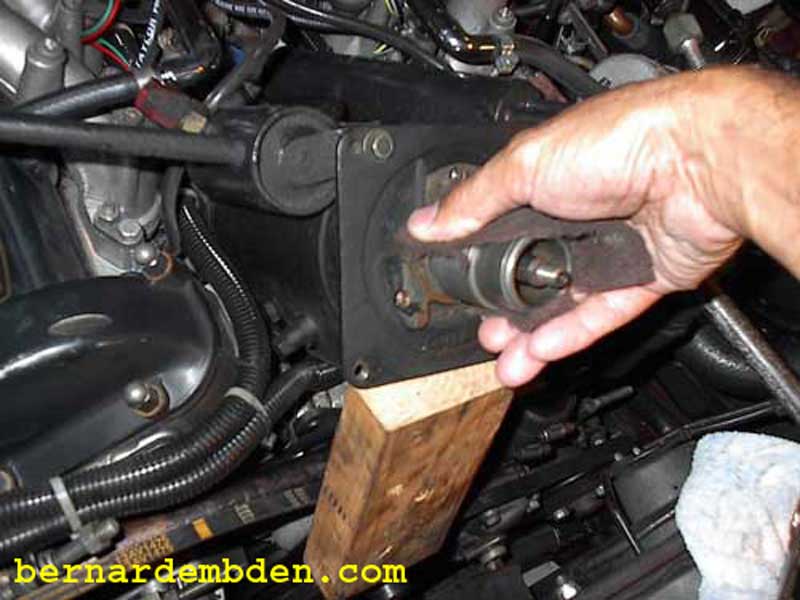
The objective is to replace the AC clutch on the car. Remove the AC compressor's front and rear bolts only. Lift the front of the compressor up to clear the top radiator support. Maintain the compressor in that position by placing a block of wood between the front of the compressor and the top of the engine. Do not depressurize the system or remove any hoses.
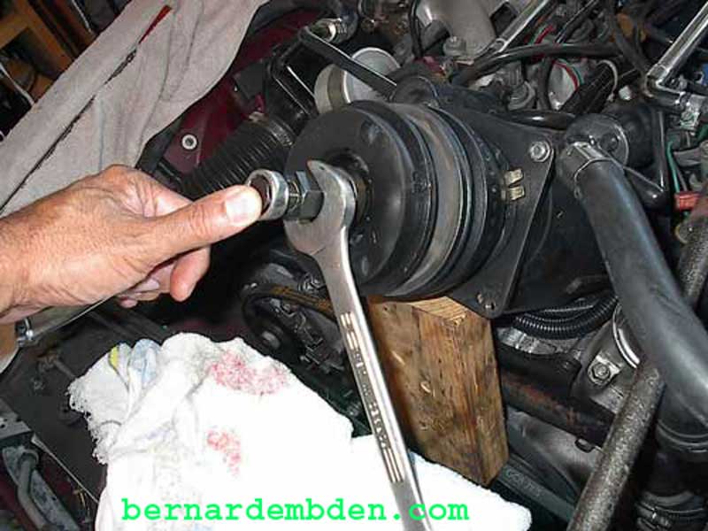
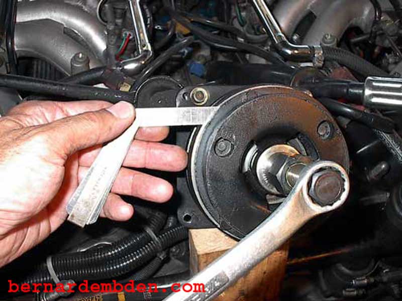
Remove the center 9/16-inch nut from the compressor shaft. A special clutch holding tool is not needed if an air impact wrench is used.
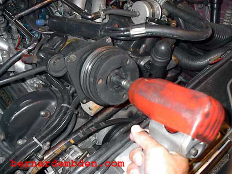
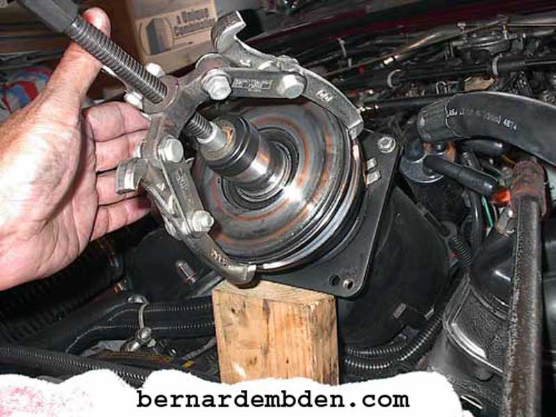
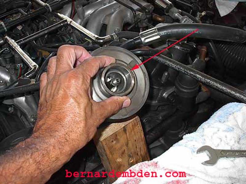
Offer up and install the clutch removal tool. The clutch is a "press fit" to the AC compressor front shaft.
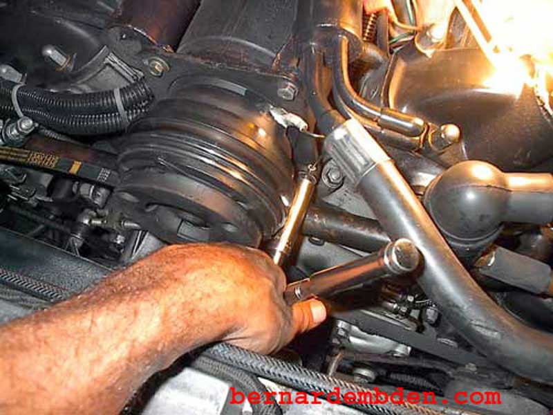
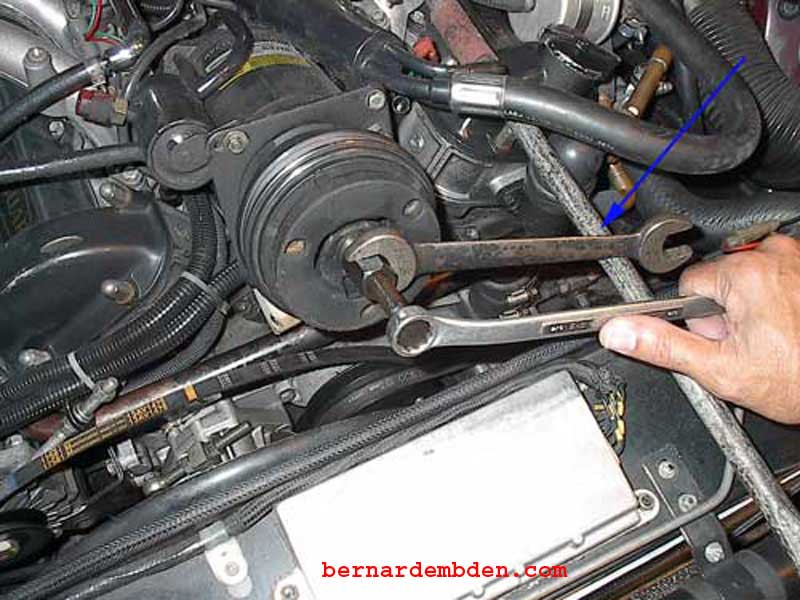
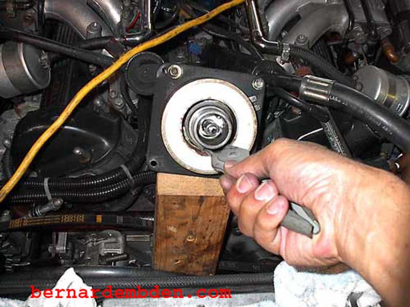
Instead of a clutch holding tool, I used a bar resting on the engine (blue arrow) to hold the tool removal nut while I turned the center stud that forces the clutch off.
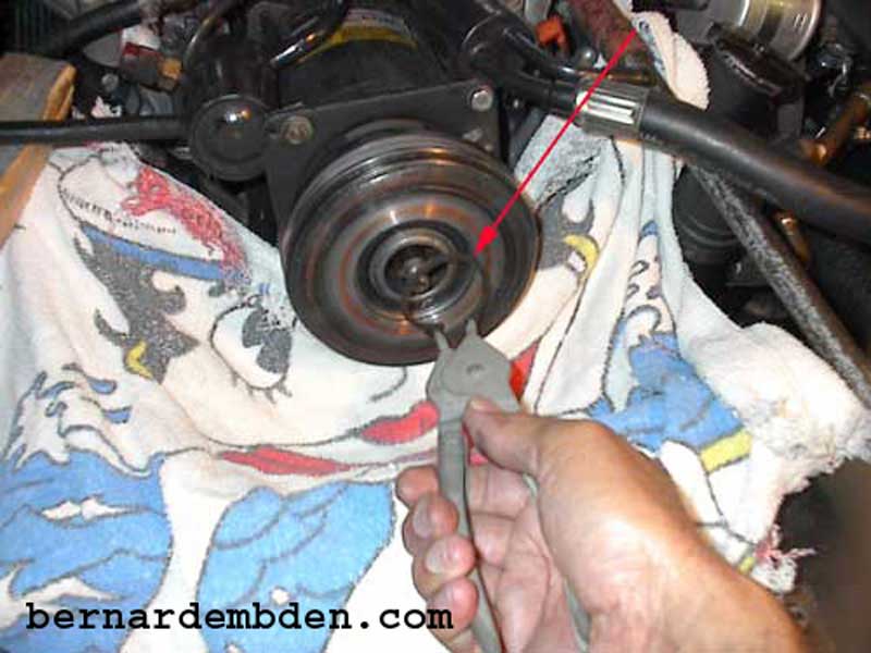
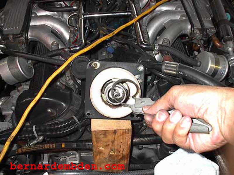
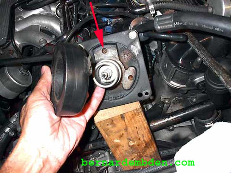
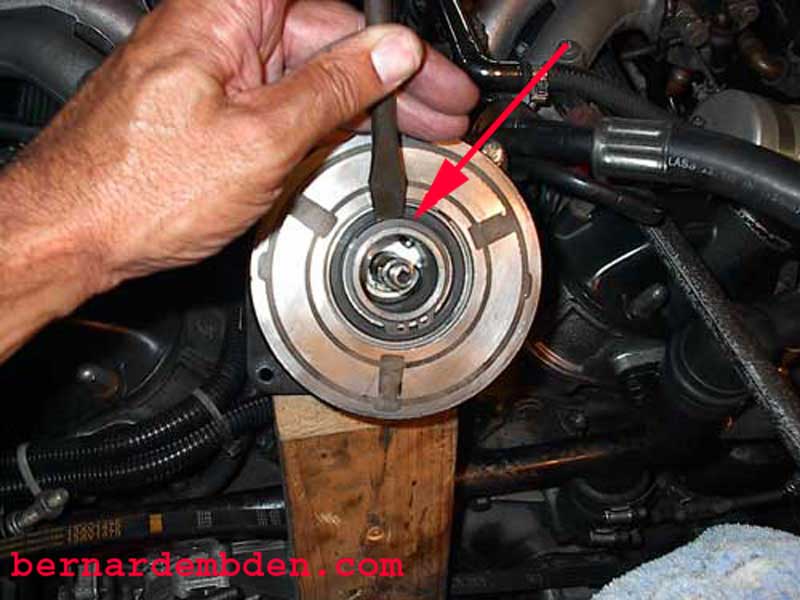
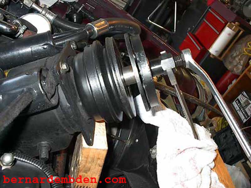
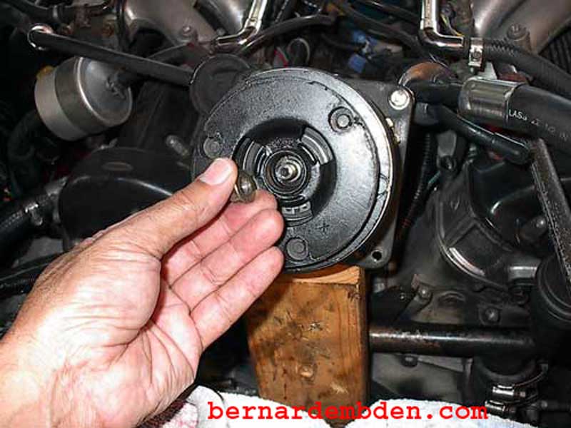
The pulley is now completely visible. You will need a large snap ring pliers to remove the snap ring that secures the pulley.
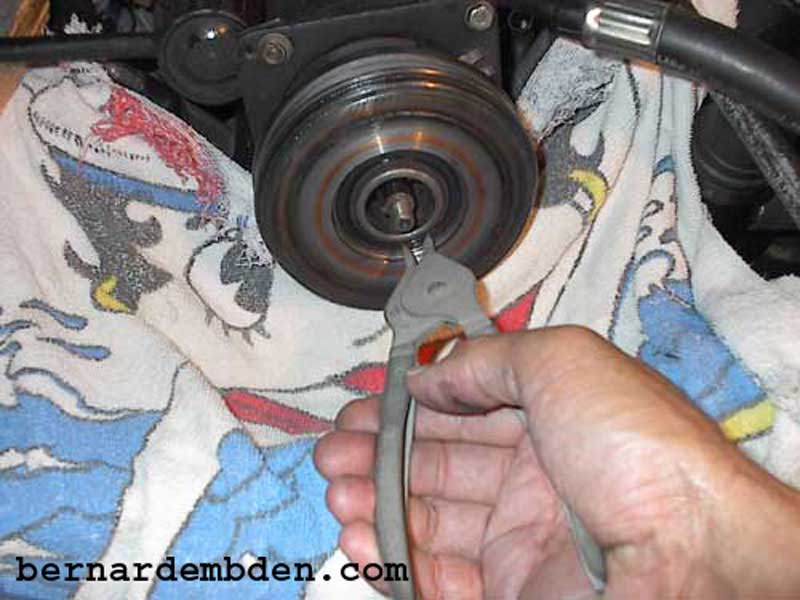
Notice the towel below the compressor. Snap rings (red arrow) have a habit of flying off the pliers and disappearing forever into the nooks and crannies of the engine. You are forewarned
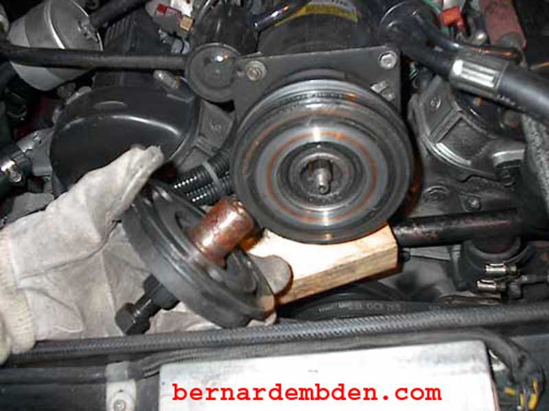
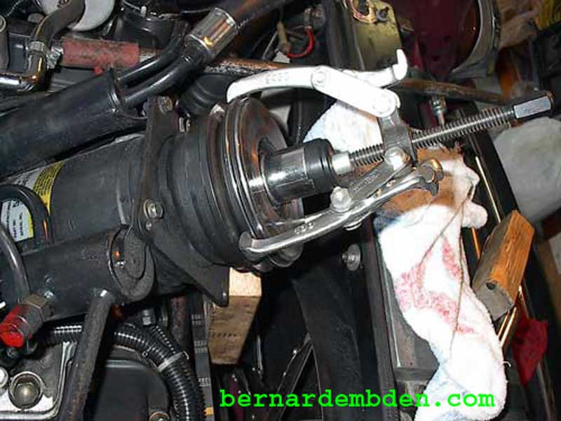
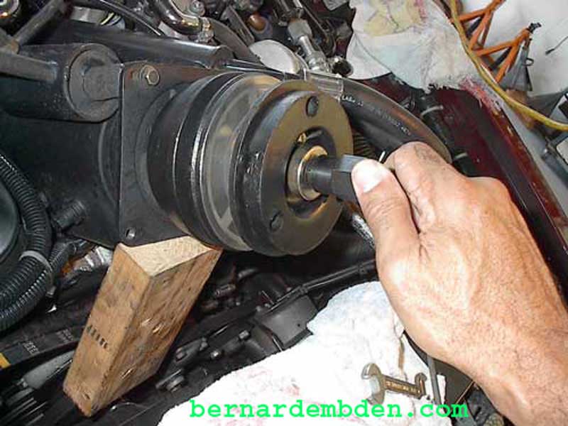
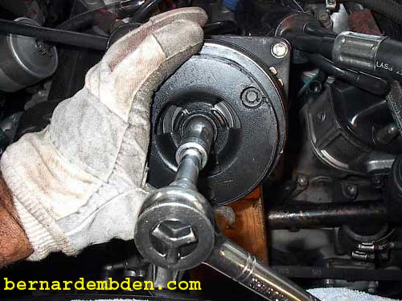
The pulley is a zero clearance fit to the compressor nose. If you are lucky it will slide off by pulling on it. You will probably not be lucky. I used a puller to remove the pulley. Be careful here. You must identify what the puller can and cannot push against. The center compressor shaft must not be used as leverage to pull or push any component not on the compressor shaft. A 1 1/8-inch, 1/2-in drive socket (red arrow) will fit over the center shaft and rests on the compressor nose cone. This is my leverage point. I taped a large washer (blue arrow) to the socket to provide a contact point for the puller.
Attach puller jaws in the pulley groves and place the modified washer to rest against the nose cone. Slowly tighten the puller to remove pulley.
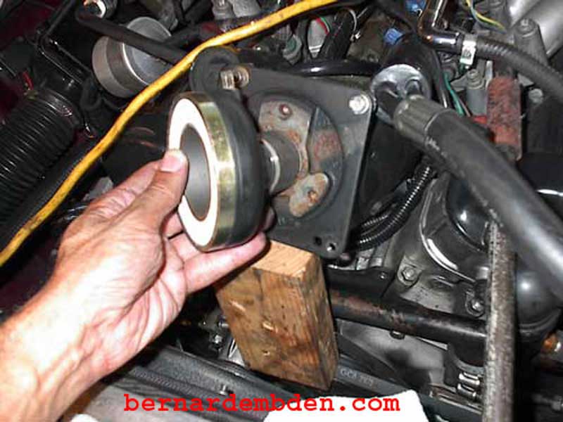
Locate and if necessary secure pulley key. If the key stays on the compressor shaft, do not remove it. An even bigger snap ring secures the coil assembly to the compressor. Remove the snap ring.
Remove coil assembly.
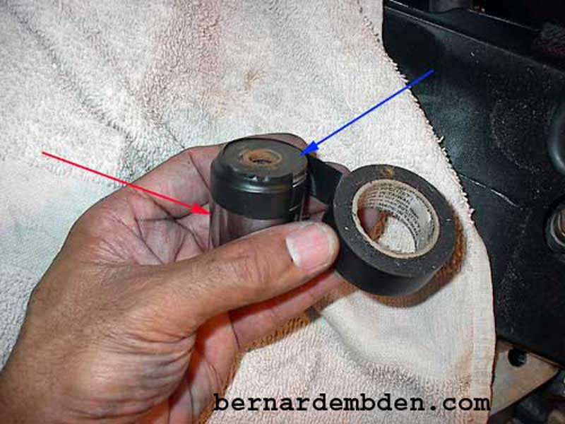
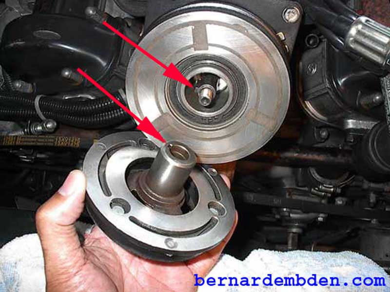
Examination of the old pulley (blue arrow) and clutch (red arrow) offers no clues as to why they malfunctioned. There is some oil residue on the pulley face, but the surfaces appear to be OK.
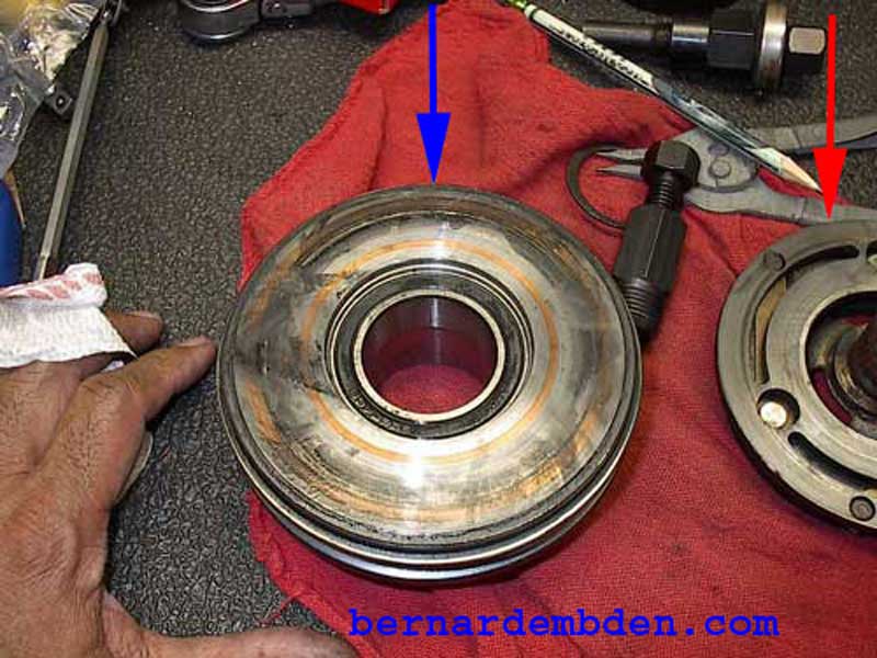
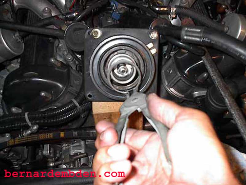
The clutch release springs (blue arrows) also appear to be in working order.
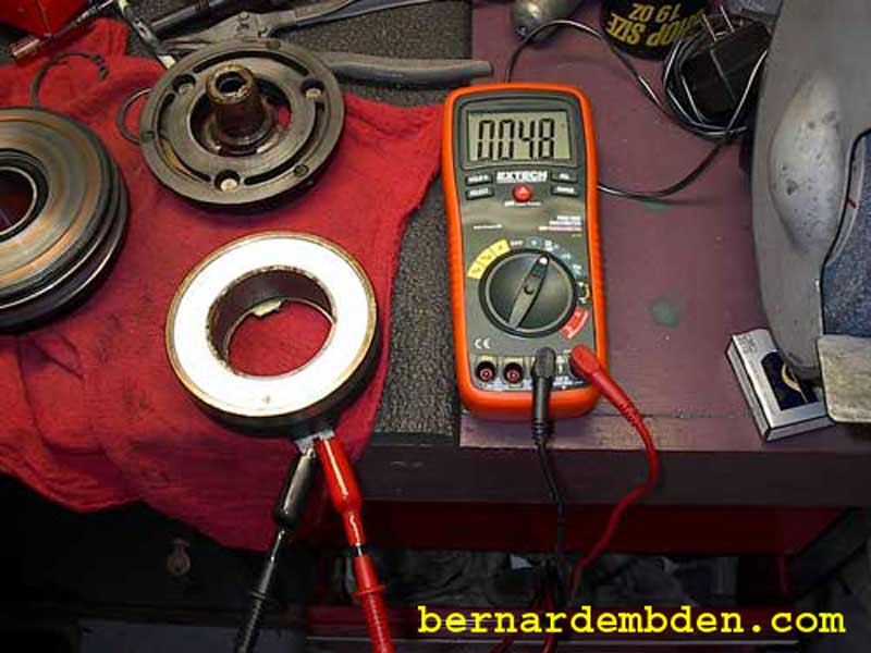
Testing the resistance of the coil assemblies indicate that they are within specs. The old coil pack reads 4.8 ohms.
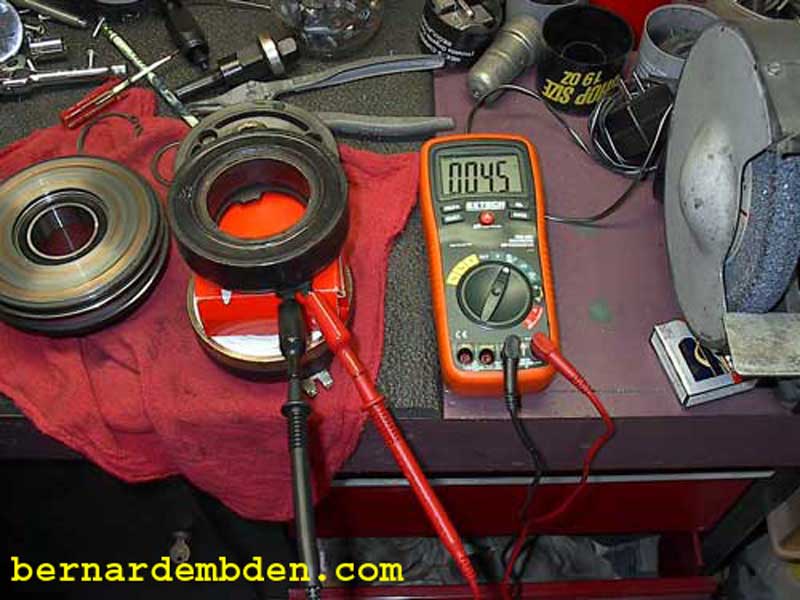
The rebuilt coil pack reads 4.5 ohms.
In removing the clutch it appeared the coil was permanently energized. The clutch removal tool had to forcefully pull the clutch from the pulley. I was not about to put this evil coil pack back on. I cleaned the contacts on the rebuilt unit prior to installation.
Gently clean the nose cone (I used a scotch pad) to remove any surface rust. Don't be aggressive here, the clutch bearing rides on this surface, it must not be compromised.
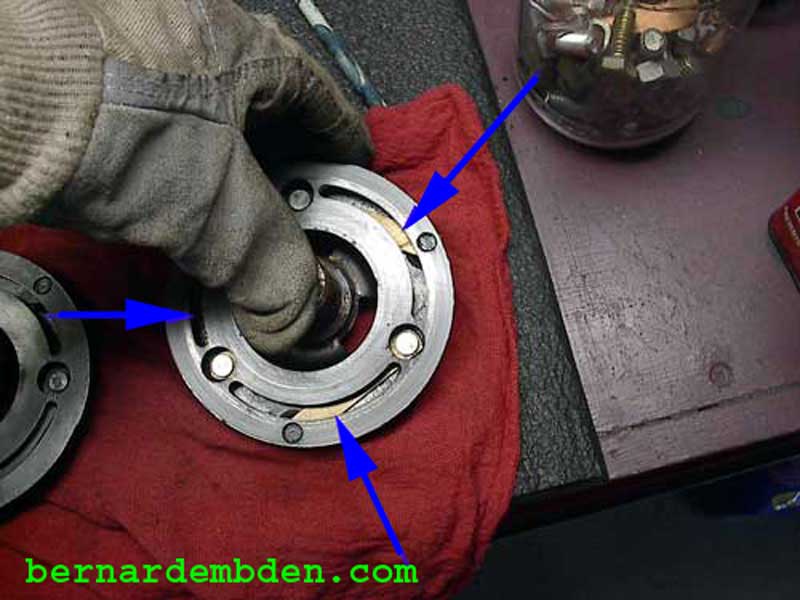
Offer coil pack to compressor and install. Make sure the coil pack is orientated properly to connect the electrical connector. There are three projections on the rear of the coil pack that must match the corresponding holes in the compressor body (red arrow). Install big snap ring.
Clean pulley surface and install pulley. The bearing might require some slight persuasion to slide onto the nose cone. Use a drift (red arrow) that contacts the inner ring of the bearing only. Tap gently until the pulley bearing seats.
Install second snap ring. Make sure that the snap ring seats fully in the shaft grove. Tap the snap ring fully into the groove with a screwdriver if necessary. (red arrow)
Clean clutch mating surface and offer clutch to the compressor. Note position of shaft key and corresponding clutch key slot. (red arrows). Make sure they line up before installing clutch to compressor shaft.
Offer up clutch install tool. The front of the tool (blue arrow) screws over the threads of the exposed 9/16-inch shaft stud (yellow arrow). The nut then forces the bearing (red arrow)against the clutch face, forcing it onto the compressor shaft. One side of the bearing rotates with the nut to reduce friction as it forces the clutch onto the shaft. Note that the forces all act on the compressor shaft, not against it.
Hold the center bolt while incrementally tightening the nut down.
You are looking to establish a clutch to pulley clearance of .010 to .015. If you inadvertently create too close a gap, put the clutch puller back on and pull the clutch out accordingly. Replacement and or rebuilt parts are rarely perfect. You will probably get different readings at various locations around the circumference of the clutch. If the closest gap is .010 or more and the largest gap is .015 or less you are OK.
Install 9/16-inch self-locking nut and tighten. If a clutch holding tool is not available, then finish tightening this nut after the compressor belt is on and the clutch energized. This nut does not hold on or impacts the position of the clutch. It appears to be a safety precaution just in case the press fit clutch somehow comes off the compressor shaft.
Install compressor to engine. Tighten 4 bolts to engine bracket. Connect electrical connections to coil assembly. Install belts.
Project complete.
