The Jaguar Pre-HE V-12 engine signals injectors in banks of three. All 12 injectors are controlled by four signal wires from the amplifier. Testing the pulse duration of the fuel injectors via these signal wires is a necessary function whenever diagnosis of the air/fuel mixture is required.
My current method of either pulling off an injector plug, or piercing an injector signal wire was unacceptable. In addition there was no easy way of testing all four signal wires to determine if any variation in signal width existed.
While rebuilding my fuel injector harness a unique opportunity presented itself for me to install a fuel injector pulse width duration test block.
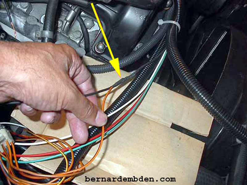
(While building a new fuel injector harness) During the connection of the new fuel injector harness to the existing amplifier plug, I soldered a bridge to the signal wire. (yellow arrow photographed below).
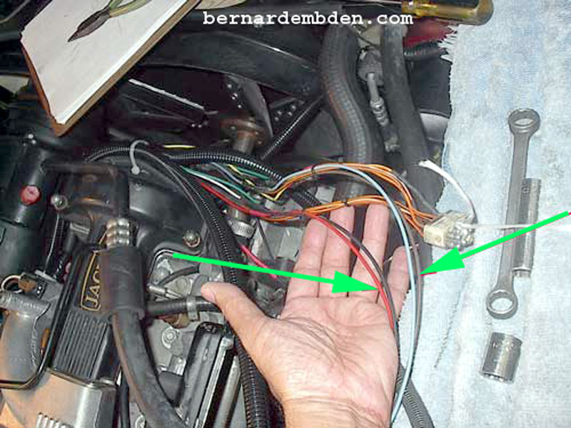
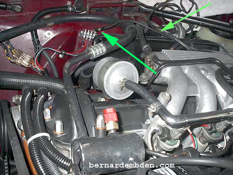
I identified all four signal wires and soldered wire bridges to them. The colors of the wires identify which three injectors they control. (green arrows photographed below).
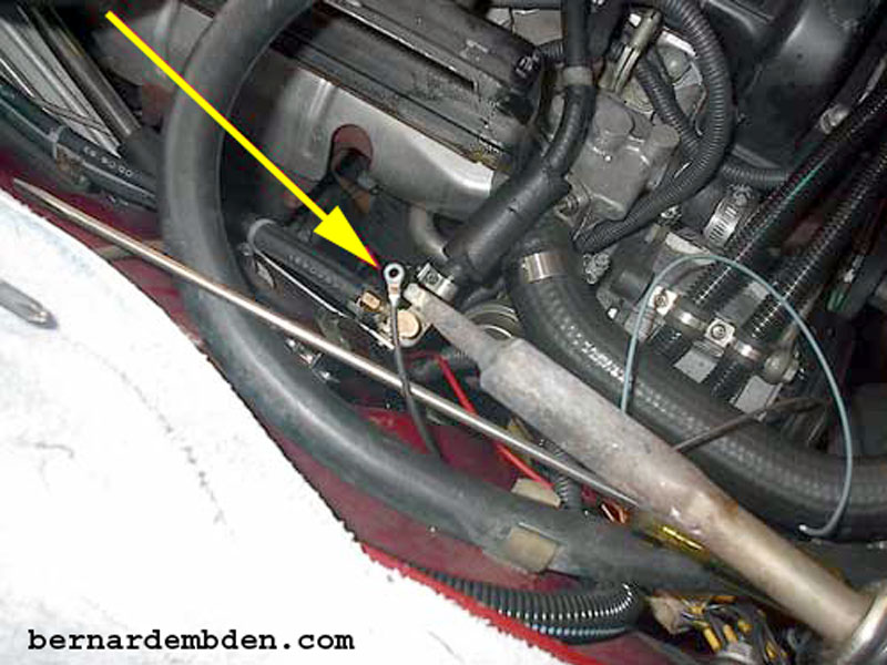
After identifying lengths, I soldered wire post connectors on the tips of the bridged wires. (yellow arrow photograph below).
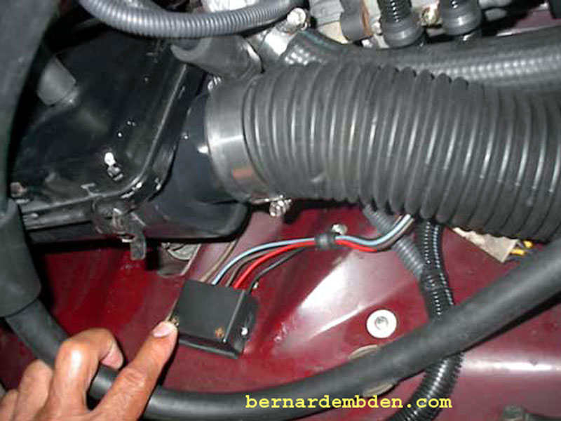
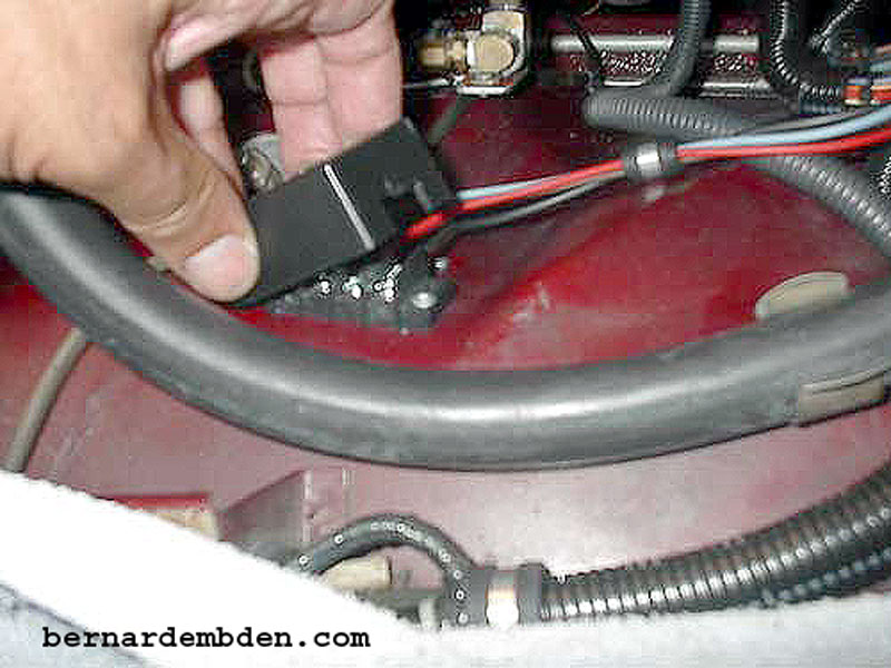
I purchased a generic 4-connection test block at Radio Shack (electronics parts store in the US) and riveted the test block on the inner wheel well of the right fender. In the photograph below, I connected the four signal wire post connectors to the block (yellow arrow) and secured the wires with an insulated clamp. (green arrow).
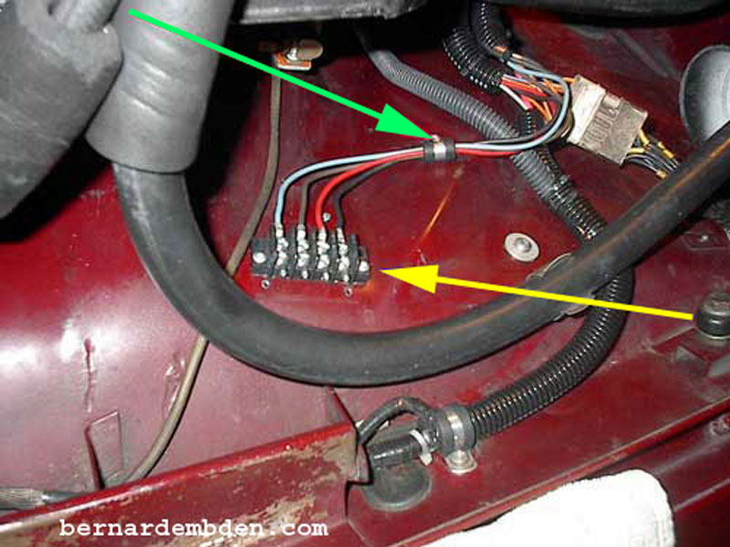
Pictured below is the wire from my pulse duration tested connected to one of the connections on the test block. (green arrows). Each connector represents a signal to one bank of 3 injectors.
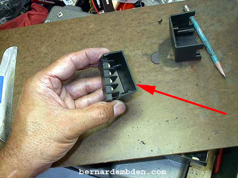
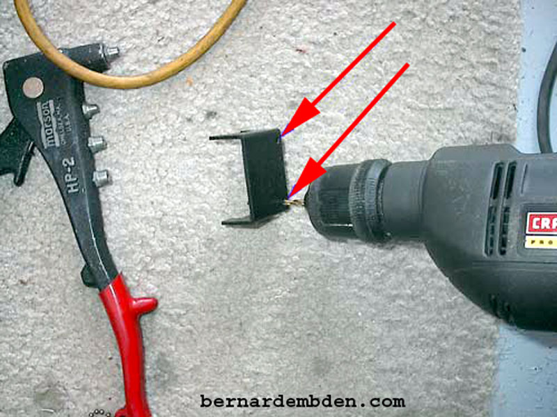
The test block should be covered. The cover was sourced from Radio Shack, however it needed modification. I cut slots in the cover (red arrow) that would allow the test block (yellow arrow) to fit into the box.

The original cover is way too big. I needed to cut in half.

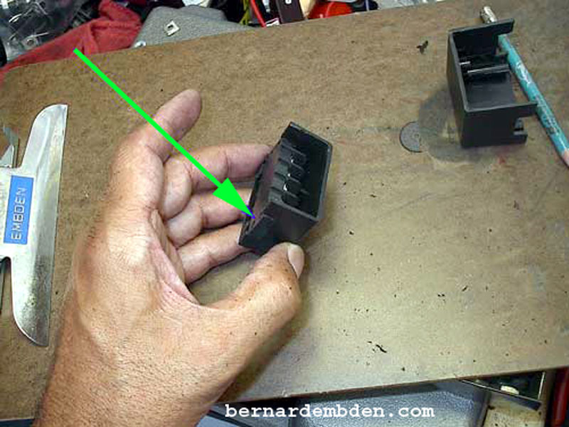
In the photographs below, the cover (red arrow) should fit snugly around the test block. (green arrow).
The next step was to drill two holes at the very top of the cover. (red arrows)
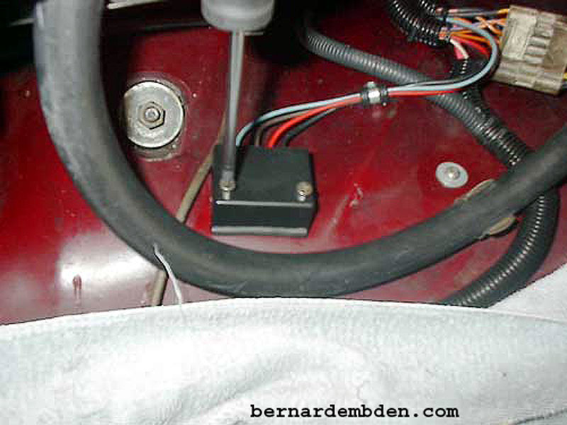
The cover is installed over the test block.
After pre drilling through the holes in the cover to the test block, I used two stainless self-tapping screws to secure the cover. (photograph below).
Fuel injector pulse width duration signal test block complete.