
The Fog light switch on my 1978 Jaguar XJ-S does not work.
The switch is clearly marked "Fog Lights" however, inexplicitly, the light switch will not rotate pass the headlamp position.
An aftermarket switch currently turns on my fog lights. I decided that the time had come to activate my fog lights through the headlamp switch as was the original design.
Note: This fog light switch is designed for the fog lights only. Rotating the switch to the fog light on position turns off the headlights. If you want both headlights and fog lights on at the same time, this modification is not for you.
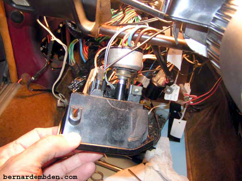
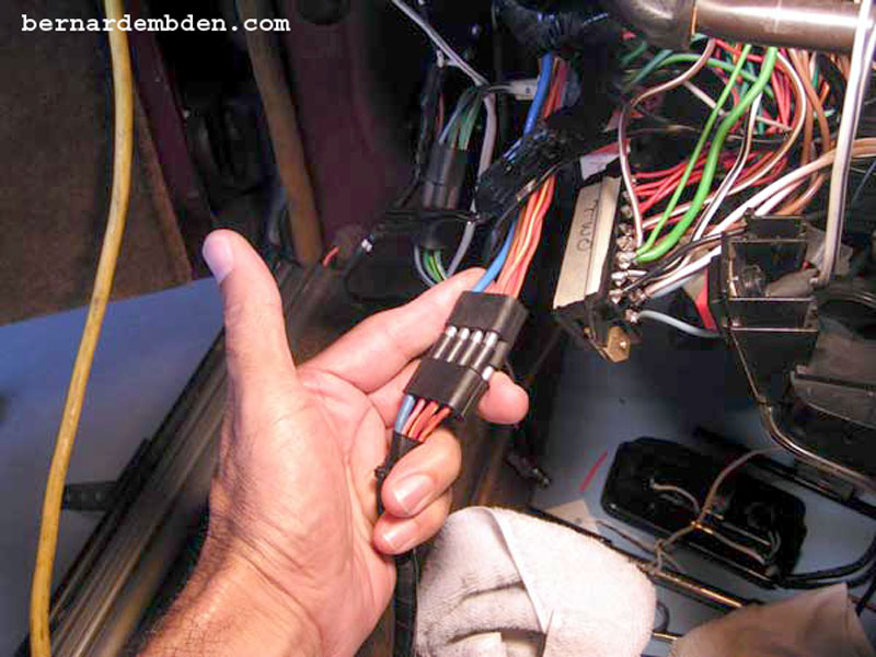
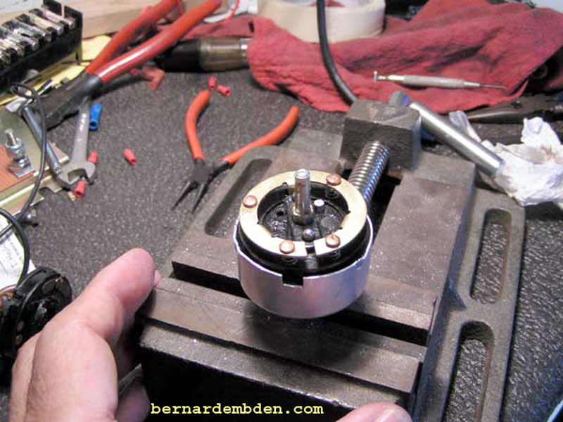
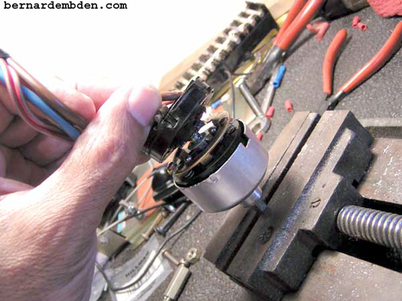
I started by taking off the driver’s side (US) dashboard under panel and removing entire headlamp/fog light switch assembly bracket. (photographs below).
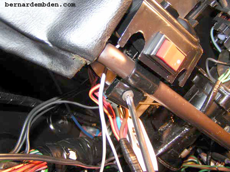
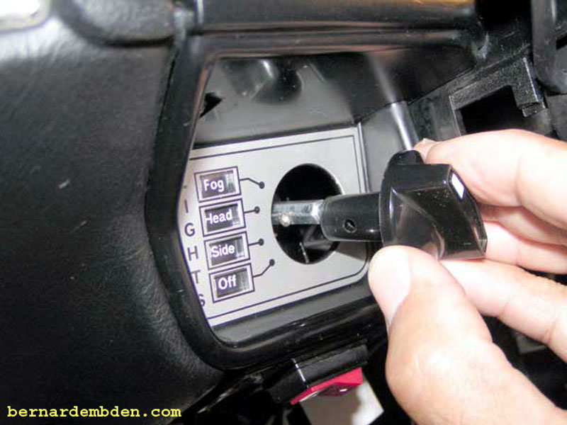
This allowed me easy access to remove the light switch knob. The knob is held onto to the switch shaft by a spring loaded pin that fits into a corresponding hole in the knob shaft. I used the point of my continuity tested to depress this locking pin while simultaneously withdrawing the switch knob.
Remove nut that holds switch to bracket.
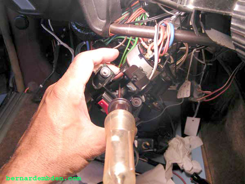
Unplug headlamp/fog light switch wiring harness.
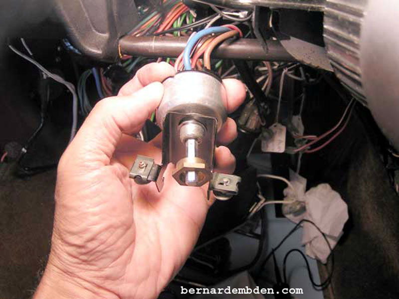
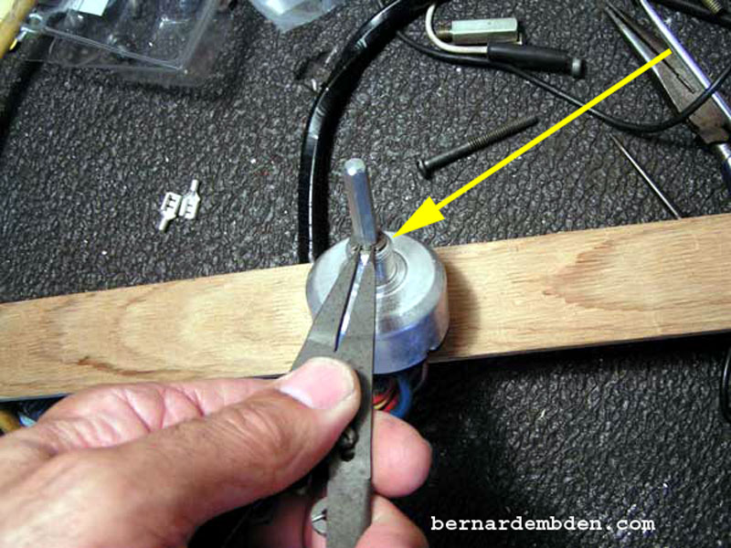
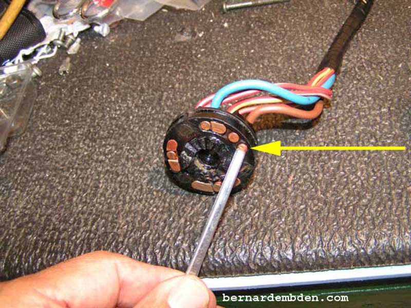
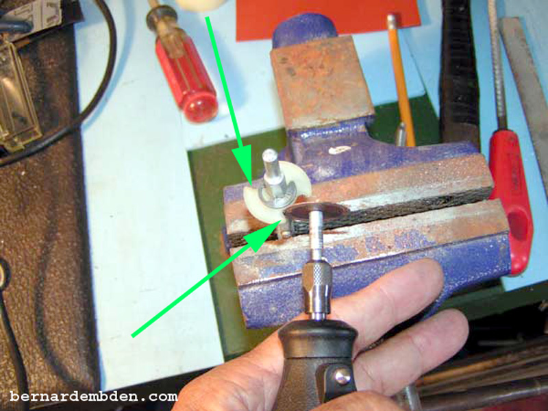
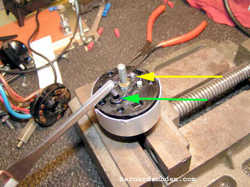
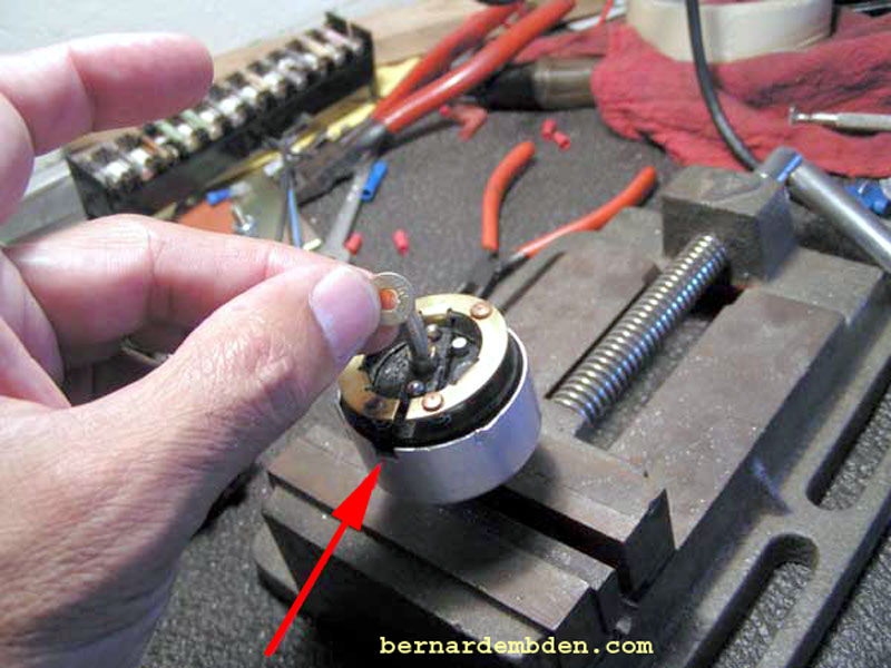
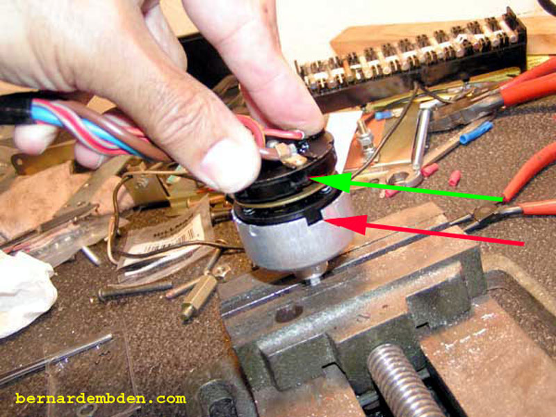
Position the switch on a work bench and remove the "C" clip from the switch shaft. (yellow arrow photograph below).
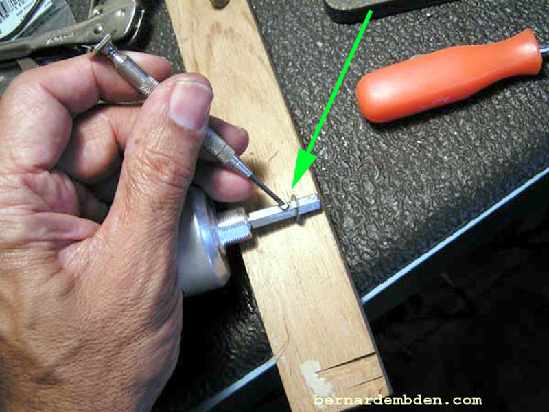
Remove the washer that is installed below the "C" clip. The knob holding pin must be depressed to get the washer off the switch shaft. (green arrow photograph below).
Project completed.
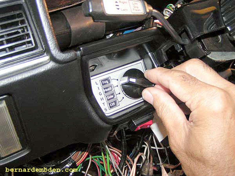
Test by rotating the switch to the headlamp on position. Because of the removal of the "C" clip and washer, the switch shaft now can be depressed into the switch. At this point the switch can be rotated further to the Fog Light "on" position.
Why was I was not happy?
What was this, a kid proof switch? I might inadvertently turn on the fog lights when I really wanted headlights? I think I know what lights I want on, and when I want them on. I don't need someone protecting me from myself, telling me that I have to do something unnatural just to turn on my fog lights.
You know the next step. I was going to take apart the switch and modify this thing to work the way I believe an adult would want it to work.
A word of caution, the next step is significant. If you are not a risk taker you might want to stop here, re-install the switch and drive safe.
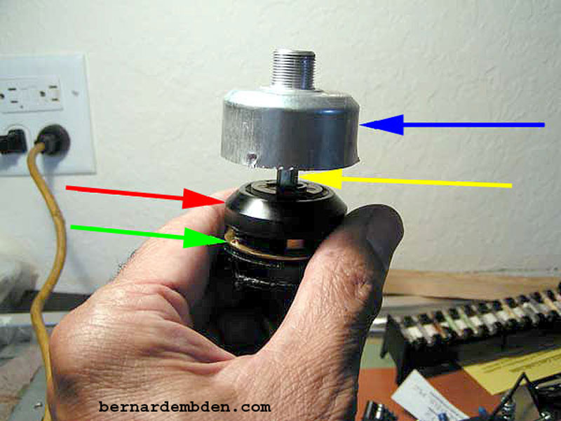
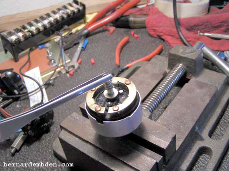
Here we go. There is no need to mark the clock position of the outer casing and switch base. It is keyed and will only install one way.(photograph below). It's important however to mark the switch shaft (red arrow) in relationship to the outer casing. (green arrow).
Rotate the switch to the headlamp on position and mark the relationship of the knob locking pin to the outer casing.
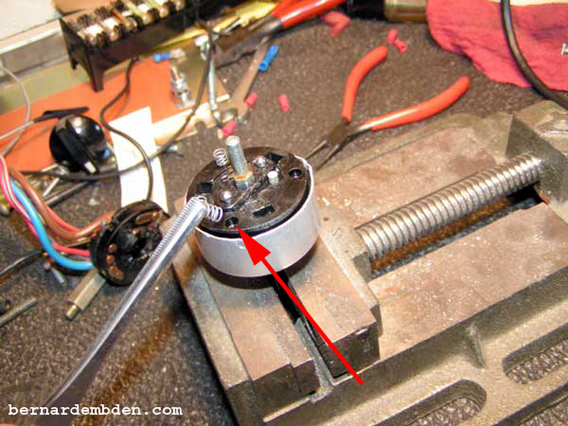
The outer casing is held on to the switch base by dimpling the case into notches manufactured into the switch base. I used a small pair of pliers to straighten out these dimples. (blue arrow)
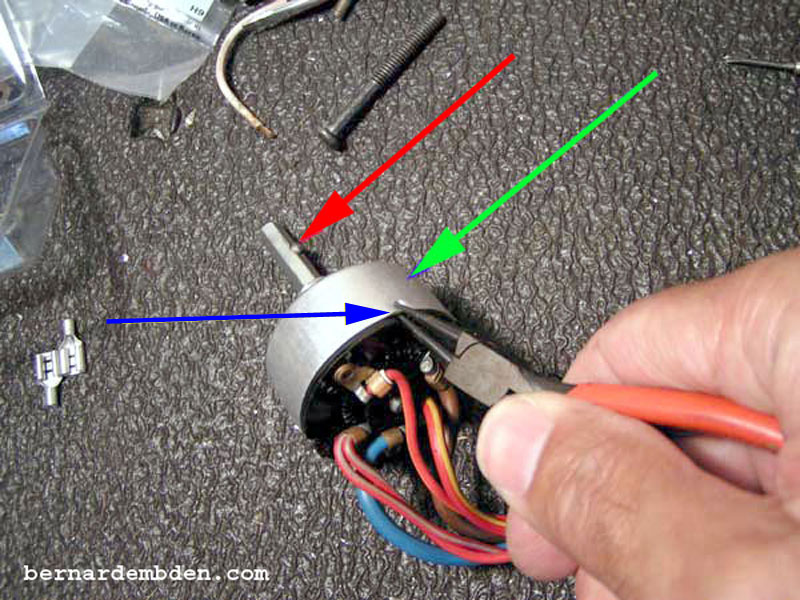
Holding the switch in an upright position, slowly withdraw the outer casing from the switch base.
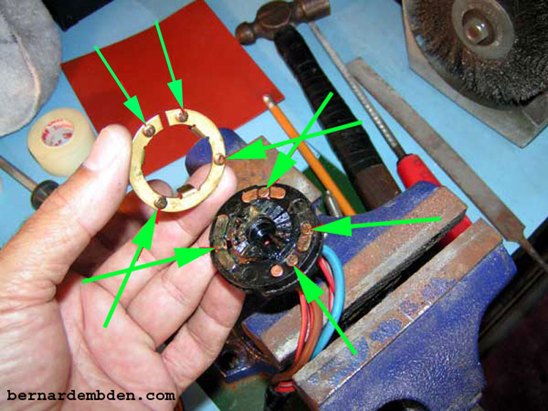
For the purpose of this project the following are identified as:
Blue arrow. Switch outer casing.
Yellow arrow. Switch shaft.
Red arrow. Switch actuator
Green arrow. Contact ring.
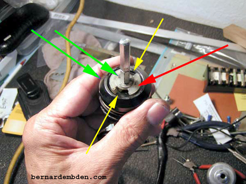
In the photograph below, you can now see the kid proof device. The plastic ring, (red arrow) that is secured to the switch shaft with a "C" clip has two notches (yellow arrows) 180 degrees from each other. These notches stop the rotation of the switch knob.
Mark the relationship between shaft pin ring and the switch actuator. (green arrows)
In a perfect world all you would have to do is withdraw the switch shaft and modify the notched plastic ring. This is not a perfect world. When the switch outer case was removed from the base, all the contacts under spring compression were compromised.
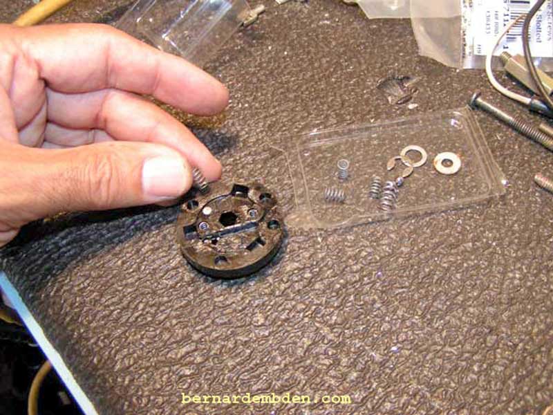
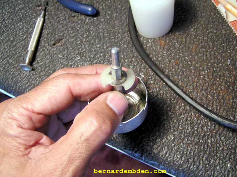
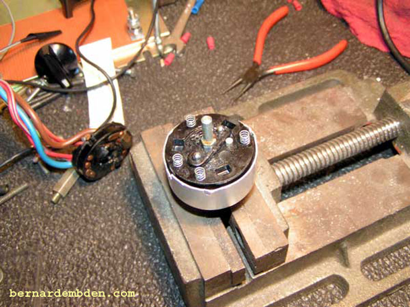
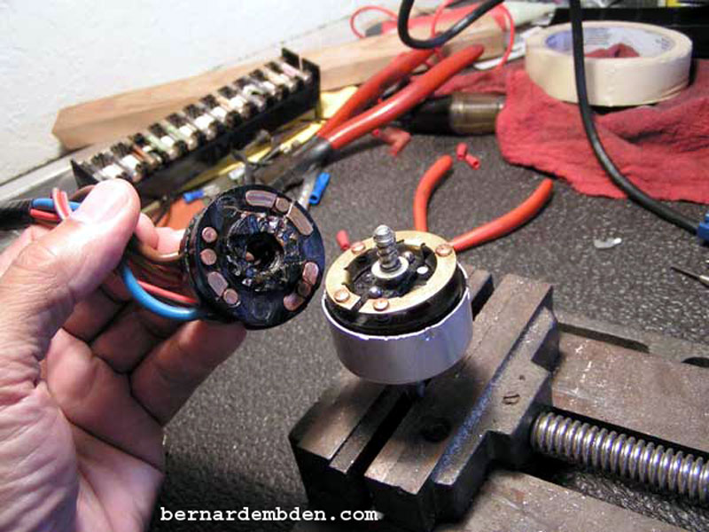
Position the switch assembly over the work bench (to catch stuff when it falls) and carefully turn the switch assembly upside down. Remove the switch base. Remove the spring and washer from the bottom of the switch shaft. Remove the switch shaft. Be prepared for springs and small metal balls to cascade from the assembly. Photographed below is the switch base and contact ring as it was removed.
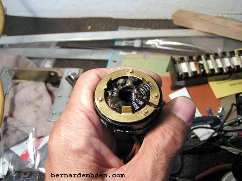
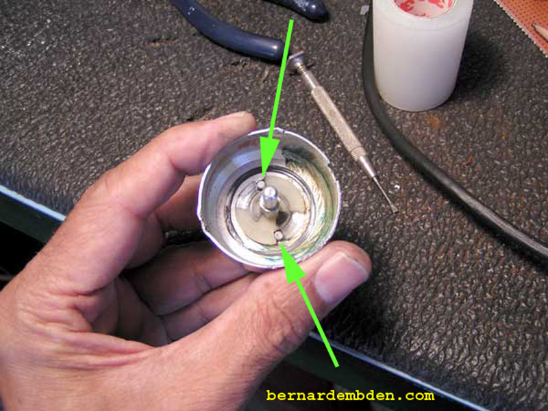
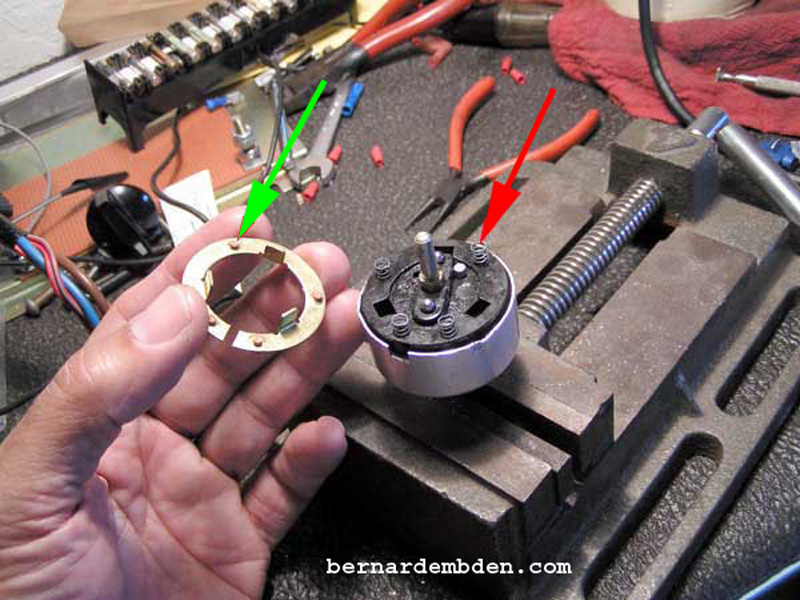
Remove the contacts ring. Observe the relationship between the contact ring and the switch base. In the photograph below, the green arrows show the position of the contact ring contacts on the base contacts when the switch is in the "headlamp on" position.
Remove and collect the springs and balls. You should have the following:
From the switch shaft one spring and washer.
Four intermediary sized springs.
Two small springs.
Two small metal balls.
If you do not have these parts, you might want to source the part number for this switch in anticipation of purchasing one.
Position the center shaft into the outer casing. Note that the two notches in the plastic ring (red arrows photograph below) fits around two stops manufactured into the outer casing. When the switch is rotated to the "headlamp on" position the plastic ring is stopped by the outer casing stops. Pushing down on the switch shaft moves the plastic ring down below the stops, allowing the switch rotation to continue.
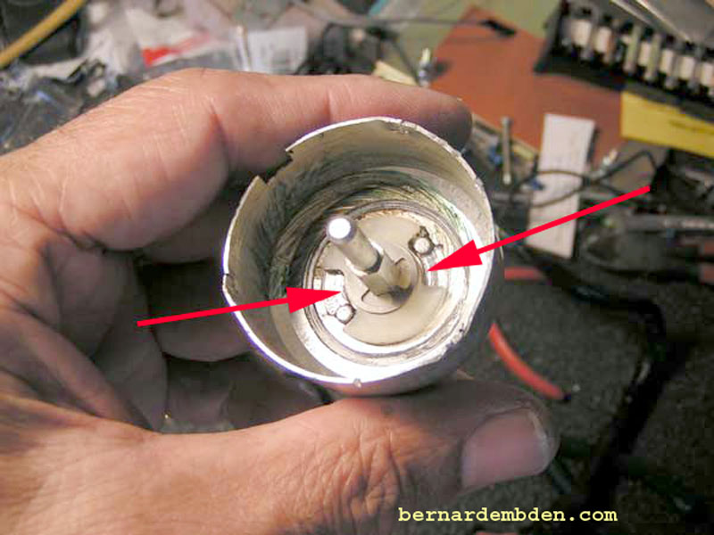
The extra rotation moves the switch contact ring allowing it to provide 12 volts to the fog light contact. (yellow arrow photographed below).
The plastic ring would have to be modified. Because the switch base will not allow the shaft to be rotated beyond the fog light on position, you might be tempted to completely remove this limiting ring. I do not recommend it. Apart from providing a nonabrasive surface to rotate the switch against, it also provides specific pressure on the contact ring.
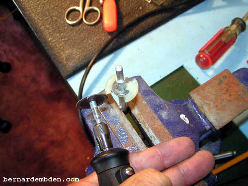
I decided to modify it. Remove and secure in a vise. Using a small cut off tool I removed 1/8 inch from both sides of the plastic ring (green arrows photograph below) allowing it to rotate to the fog light position.
Test before you start. Make sure you cut off the correct sides of the ring by first making sure you have the rotation right.
Modification complete. Install into outer switch casing and test rotation.
Note rotation now goes further after modifying plastic ring. (green arrows photograph below).
Align switch shaft locking pin to mark on outer casing and install. Turn unit upside down and install switch actuator, making sure the actuator's mark lines up to mark on the switch shaft. If you have observed and or marked everything properly these steps are relatively easy.
If you forgot or cannot find your marks all is not lost. The switch actuator is keyed to the contact ring, which is keyed to the switch base. Temporarily fit the contact ring to the switch actuator and, using the ring and base switch contacts as reference, fit the base to the contact ring. Align the base to the square key on the outer casing, while maintaining your switch shaft-locking pin to the outer casing mark. When all your marks line up the switch actuator is in the correct position. Remove the base and contact ring.
(Photograph below) Begin reassembly of the switch by installing two small springs in the center (green arrow) with the small metal balls on top of the center springs. (yellow arrow).
(Photographs below) Install four larger springs in the corresponding openings in the switch base. (red arrow).
(Photographs below) Offer up the switch contact ring to the switch actuator. Note the orientation of the four projections on the back of the contacts ring. (green arrow) These fit inside the corresponding four springs. (red arrow). Carefully position the switch ring projections over the corresponding four springs. It will only fit one way.
Install the washer onto the bottom of the switch shaft. Note the square notch on the outer casing (red arrow). This corresponds to an identical key on the switch base.
Install the spring on top of the washer.
Offer up the switch base. There are four keys here. First the switch base has four contacts that correspond with the contacts on the switch ring. The second key is the square notch in the outer casing. Before installing the switch base carefully look underneath the switch to check the shaft to outer casing mark. Then check the switch actuator to switch shaft mark. Position the switch base over the contact ring based on lining up the contact ring and switch base contacts. Line up the square notches on the base outer casing. When all the keys are in sync push down and install the switch base.
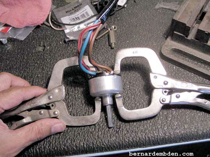
(Photographs below) Press the base firmly onto the switch. Note square notch alignments in switch base (green arrow) and outer casing (red arrow). Once the base is in do not remove pressure. I used two welding clamps to hold the switch base into the switch body. The clamps should provide just enough pressure to hold the bottom switch assembly in, but not enough to dent the outer casing.
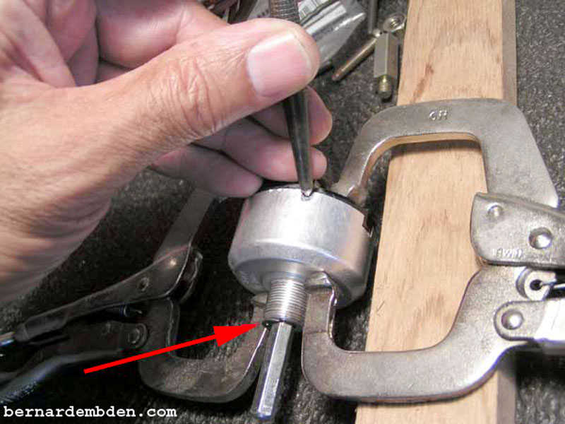
To secure the switch base, I used a punch to dimple the outer casing at the corresponding indentations. Note that the "C" clip removed earlier has been re-installed. (red arrow photograph below). Although not absolutely necessary, it holds the switch shaft in the proper position.
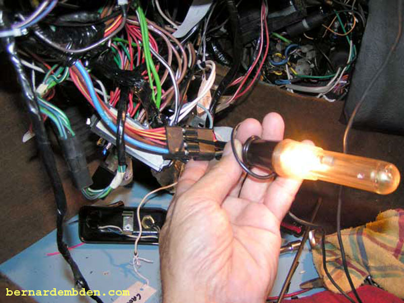
Plug the switch back into the wiring harness and test. The switch should move freely from "Off" to "Fog light on" position without binding. At the "Fog light on" position the two red/yellow wires must have 12 volts.
Install switch and knob. The knob is designed to compress and release into the corresponding hole the locking pin as it is installed.
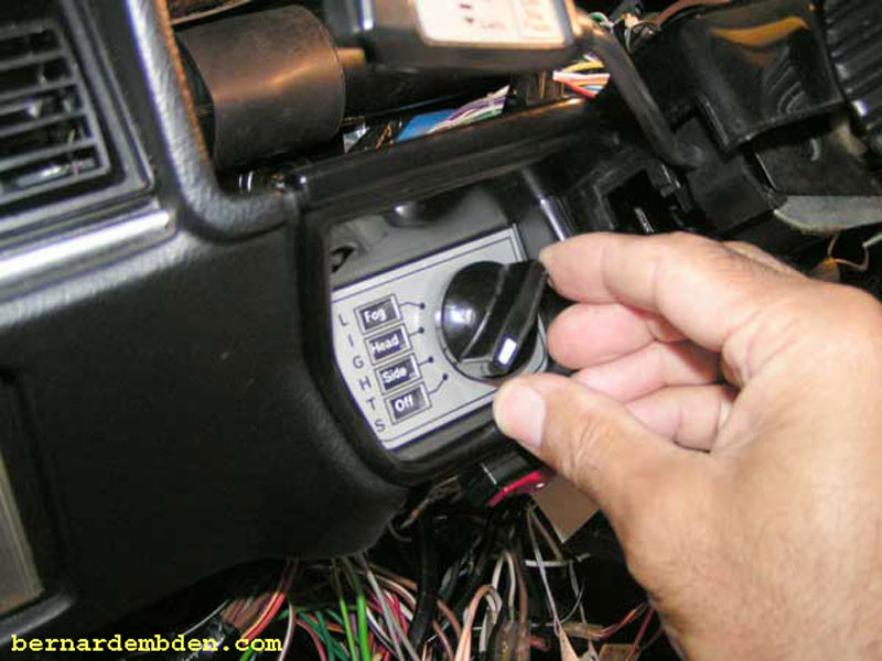
Project complete. The switch now operates the way I want it to. It moves smoothly from the off position to the fog light on position without any push pull gimmicks.
The last step in this project is not critical to the operation of the switch. It just makes me feel better.
