
This is a project that is hard to justify. Watching a fuel pressure gauge is like watching paint dry.
I keep coming back to memories of engines that had fuel pressure gauges permanently mounted on the fuel rails. I might not need that information, but I wanted that information.
On many occasions I wanted to know what the fuel pressure was, was it still correct? But do I need to know all the time? On modern cars there is simply no need for this. Either you have fuel pressure or you don't.
I do not have a "Modern" car. My fuel pressure is manually adjusted using a pressure regulator that was designed over 30 years ago and has a tendency to loose pressure in the fuel rail.
In addition injectors, controllers, sensors. amplifiers, ECU are all over 30 years old. Any diagnostics on the fuel system required knowledge of the fuel pressure inside the fuel rail.
Maybe I do need a fuel pressure gauge permanently mounted in the engine compartment.
Now that I have convinced myself that this is a necessary project, it was time to get started.
Of course, no fuel pressure gauge manufacturer that I know of recommends mounting their fuel gauges inside the engine compartment on a permanent basis. This was certainly not going to deter me.
Readers of this website will note that I have a fuel pressure gauge mounted inside the passenger compartment on the console. This gauge will replace that for a couple of reasons.
1) The current gauge uses an electrical sender to convert pressure to electrical inputs and transmit them to the pressure gauge. This is not the most accurate method.
2) The location of the sender is before the fuel rail, ideally it should be at the fuel rail.
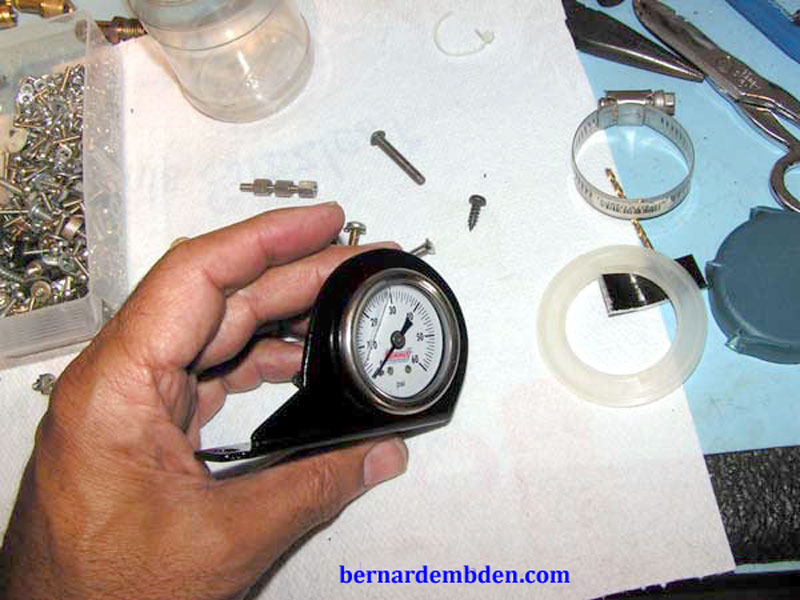
One other decision. I decided to use a liquid filled gauge. These gauges are filled partially with Glycerine, a liquid that's designed for temperature extremes. Liquid filled gauges are designed for direct mounting on equipment, as it compensates for vibration, corrosion and pulsating.
This gauge then would handle the fuel pump pulses and the vibrations inherent in a hostile engine compartment.
In the interest of safety, the gauge would not actually be mounted on the engine, rather on the left inner fender wing adjacent to the relay packs.
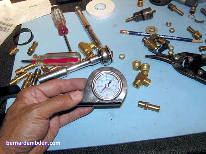
I sourced a 1.5-inch liquid filled fuel pressure gauge from SUMMIT Racing, a parts supplier of racing equipment in the US.
If you decide to install this gauge, do so at your own risk.
Project starts by fabricating a suitable mounting bracket for the new gauge. The opening and angle on the mounting bracket needs to be determined. I started out with part of an aluminum shelf left over from a prior project because it had a pre-formed angle suitable for mounting.
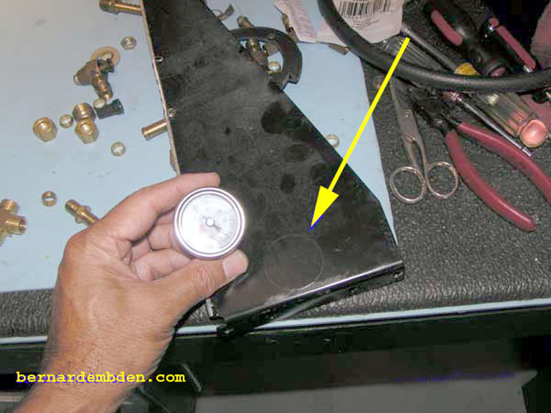
Position the gauge on the stock and mark the circumference of the gauge body, (not the bezel, yellow arrow photograph below) making sure it lines up with its final mounting position.
I used a jigsaw with a fine metal blade to cut the hole. Be careful on this, the bezel face of the gauge is quite narrow, it will not cover a sloppy cut.
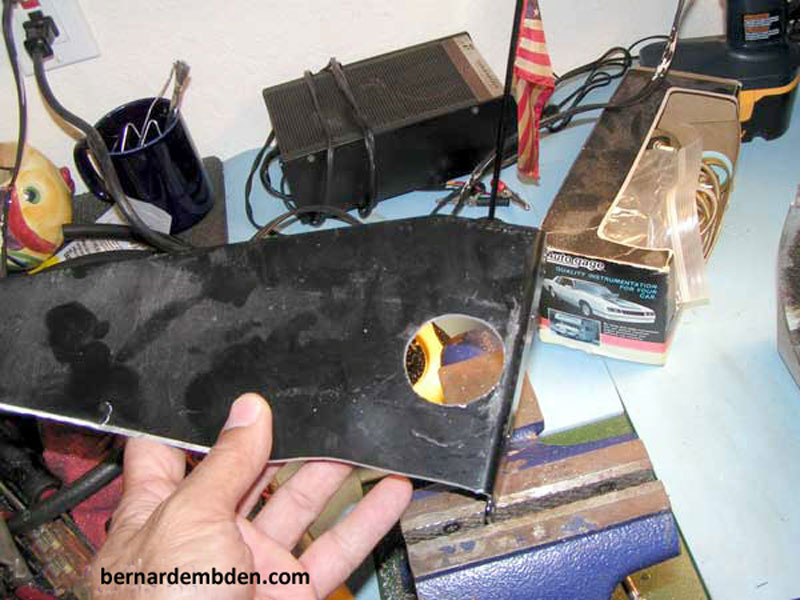
Trial fit the gauge to make sure it fits and the bezel face overlaps the opening.
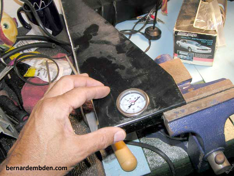
(Photograph below) I wanted the mounting flange to be offset to the left to clear the left engine brace, so the bracket was fabricated accordingly.
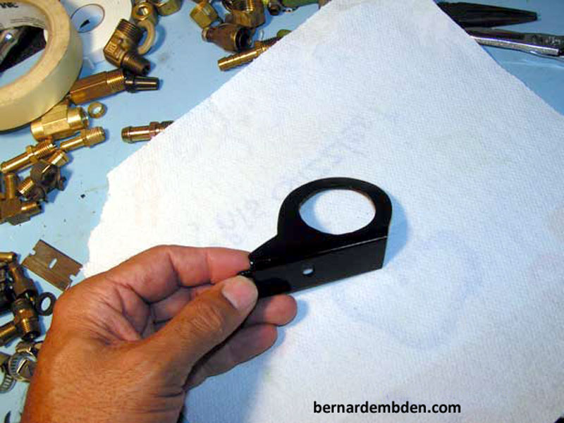
One final fitting before going to paint. (Photograph below).
If you have done this right, the painted bracket should looks as if it was made by someone who has some skill sets, not just hammered up on your sidewalk.
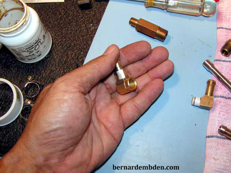
Based on the desired mounting location, there would be no clearance to attach a hose to the bottom of the fuel gauge from the fuel rail. I could not source a right angle adapter, so I made one up from two different fittings. (photographs below).
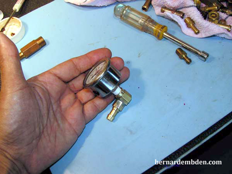
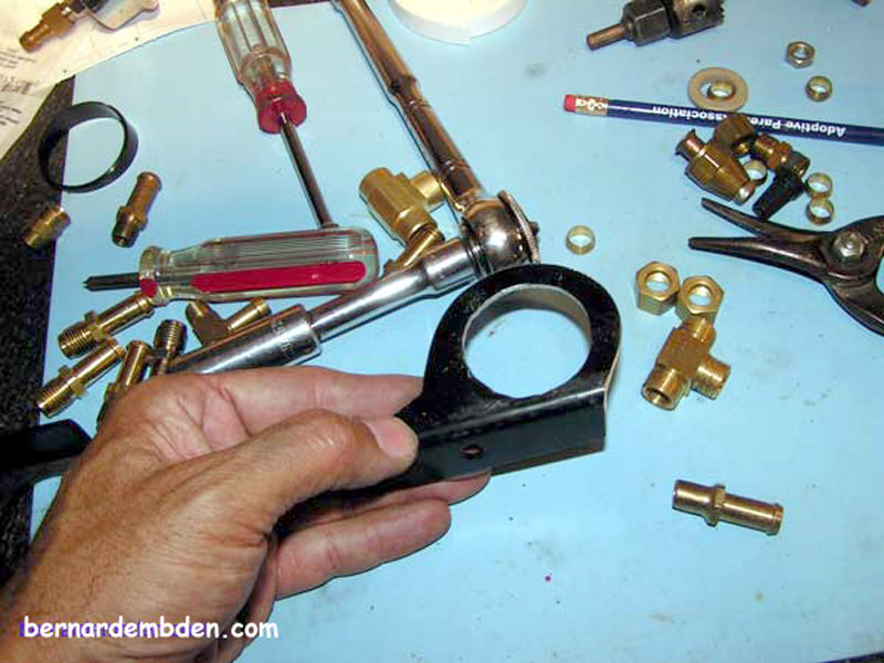
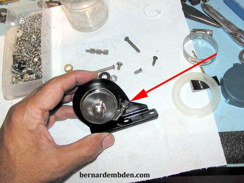
Final fitting of gauge to bracket. (photograph below) There will be no clearance for using any normal mounting methodology. A substitute mounting method would have to be created to secure the gauge to the custom bracket.
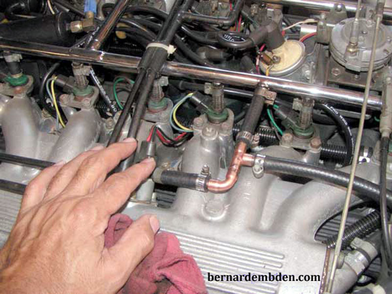
I wanted the gauge to read directly off the fuel rail. That would require a connection at the rail itself. For the Pre-HE engines, the cold start injector hose connection is ideal.
I bought some copper "T" and hose connections at the local automotive store and mucked a "T" fitting up that worked but looked like crap. Actually, it was not quite that bad, but the scale was off, the fitting was just a little too big to look just right once it was installed.
If you have been looking at this website, you know these modifications not only must work, they need to look good.
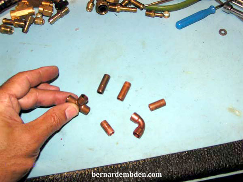
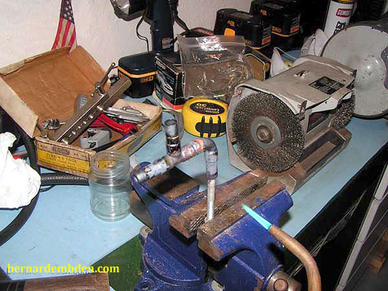
So it was off to the plumbing store for stuff. These fittings (photographed below) are used for home air condition systems and would be the perfect scale for this project.
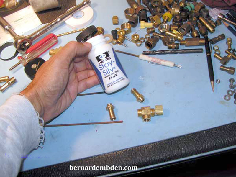
Note: You must braze and or silver solder any fitting carrying fuel and living in the engine compartment. Even though unlikely, regular solder can melt during the heat soak from a V12 engine. It will ruin your day.
Photographed below are the flux and brazing rods that will be used on this project.
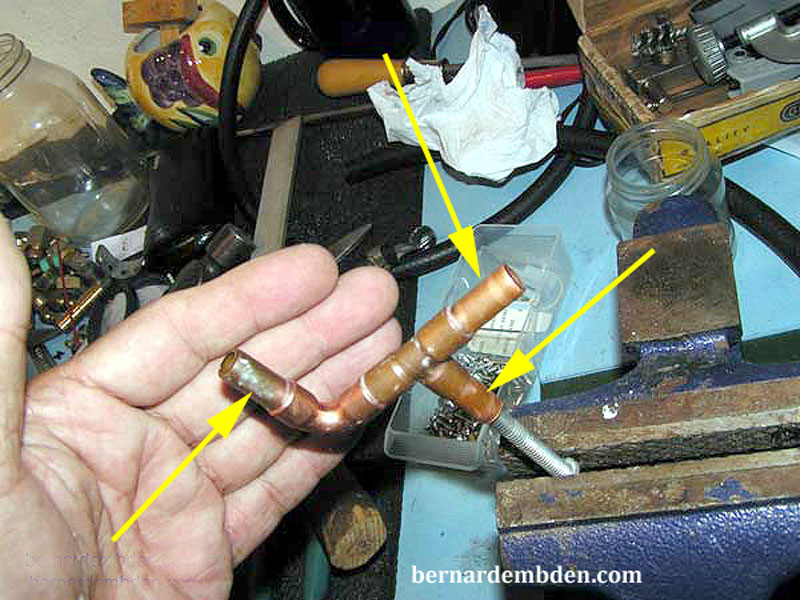
Measure and cut the copper pipe, making sure all angles are oriented correctly. I leave at least 1.5 inches of pipe exposed to insert into the fuel hose. (yellow arrows photograph below).
If welding or brazing (photograph below) is not your thing, take it to a professional. Don't skip on this, or use an off the shelf "T" fitting that might not look quite as cute, but will not burn your car to the ground.
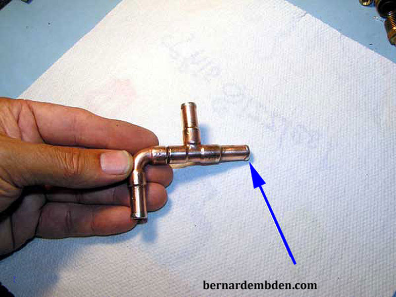
If you are fortunate and do this just right your fitting will look like the picture below. Note the "bumps" on the end of the hose connectors. (blue arrow photograph below). These are important, it keeps the clamps from sliding off the copper hose connectors under pressure. These are brazed on during the process.
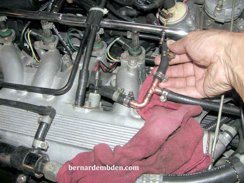
Photograph below. The custom "T" fitting is installed on the left cold start injector connection. Don't cheap out on this, use a new length of hose designed for fuel injection applications.
Prior to mounting the bracket, the gauge was orientated correctly within the bracket and secured to the mounting bracket with a narrow aero seal clamp. (red arrow photograph below). Connect 90 degree fitting (fabricated earlier) to bottom of gauge, again making sure that's orientated correctly.
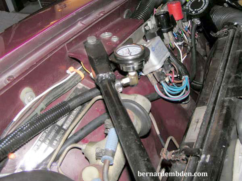
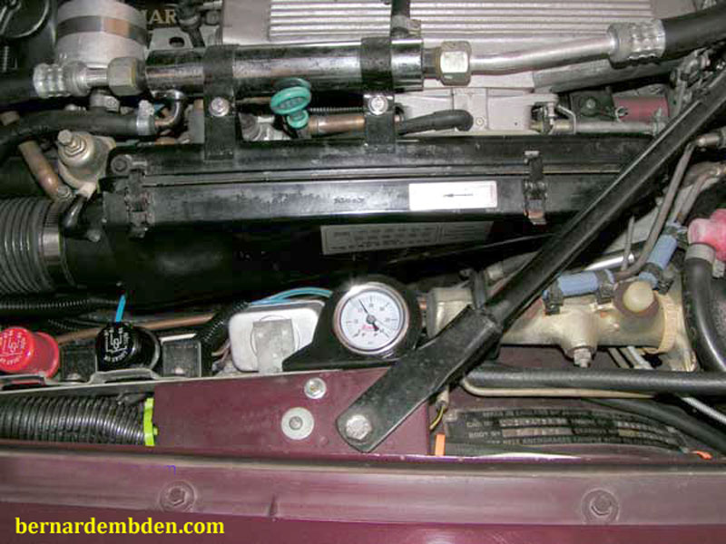
I installed the gauge on the left fender wing, mounted to the same bracket that holds all my relays. These relays were moved to this location during a prior project of sourcing outside cold air to the engine.
You can see the reason for the offset bracket, it allows me access to the bracket mounting screws on one side, while just clearing the engine brace on the other side.
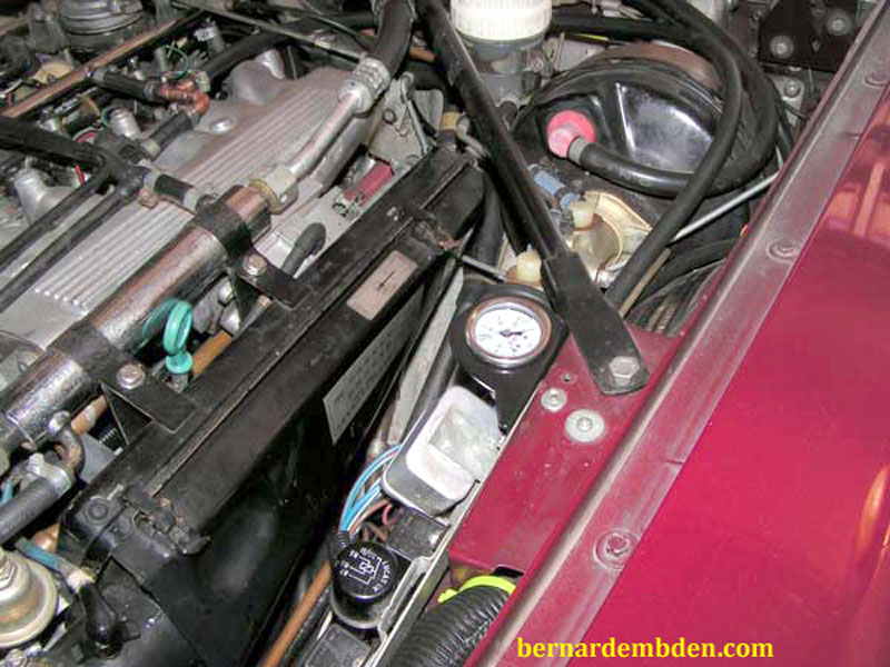
Preliminary fitting of the gauge and routing of the hose back to the fuel fail. Make sure the hose routing is such that the hose is protected at all times. Be aware of bonnet latches and throttle rods.
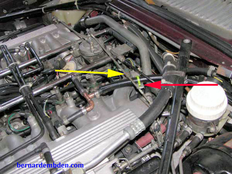
(Photograph below) I protected the hose with a small diameter wiring harness loom. The hose was just a little too close the left throttle bell rod, (yellow arrow) so I fabricated a small bracket I could tie-wrap the hose to. (red arrow) This provided the proper clearance.
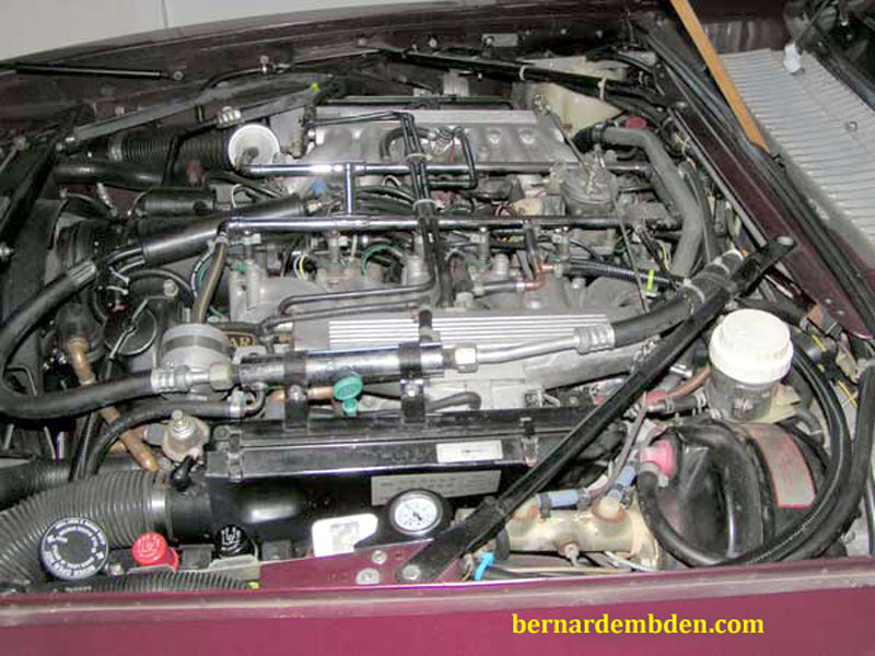
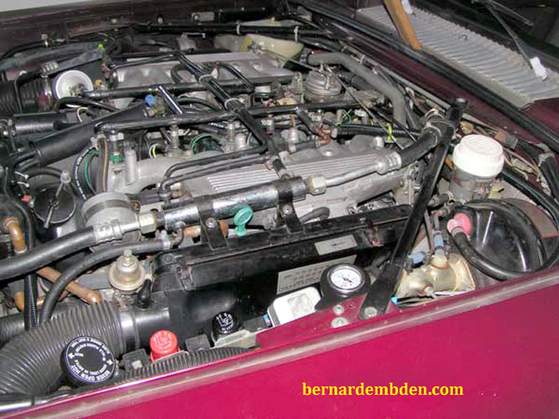
Final orientation of the gauge face so it's in the upright position when I am at the drivers side (US) of the engine bay. Tighten retaining hose clamps. Start engine and check for leaks.
Engine compartment fuel pressure gauge installation project complete.
Interestingly the new gauge, reading mechanically and directly from the fuel rail, reads 3 pounds less than the electrical gauge readings which was sourced at a point just before entrance to the fuel rail.
