

The Heater and AC blower modules in my 1978 Jaguar XJ-S were not defective. A project many years ago had resurfaced the bronze bearings which removed an annoying squeak whenever the blowers were on.
The time had come however, to replace the fuse box. And I thought "While I am in there anywhere". Few words have created more anguish than these. On a 30 year old car, "While you are in there" could take up most of your lifetime.
The Jaguar XJ-S is designed with two blower modules. Each module consist of a motor and squirrel fan mounted inside an oblong sleeve-like compartment with two doors. The doors are vacuum controlled and determines the source of air (inside or outside) drawn into the blower module. The modules are designed to allow one air source in at a time, so opening one door closes the other and vice versa.
Note that there is a difference between the early and later HVAC modules. The early module does not carry the "Darlington" control circuit. Blower speed is varied by controlled switching of resistances in series with the motors. I suspect the Pre-He cars do not have the Darlington circuits, and the HE cars do.
As is normal with Jaguar design philosophy, never create a simple solution when a highly complicated, impossible to remove, PIA design will work almost as good. As usual, Jaguar has more than succeeded in this objective.
These modules are also no longer available from Jaguar. Fortunately, a number of Jaguar suppliers rebuild these units. Unfortunately, they are expensive. Look for rebuilt modules using sealed ball bearing motors. This is an upgrade from the unsealed bronze bearings of the originals.
Did I mention they were expensive? Two rebuilt modules will leave virtually no change from $600.00 US. There is also a $200.00 core charge, refunded when the cores are returned. There was no price difference between the modules with or without the Darlington circuit. You could shop around, however I went with a reseller that I have had great success with over the years.
If you had the time to source the parts, rebuilding the Pre-HE modules are not that difficult.
I do not have the time.
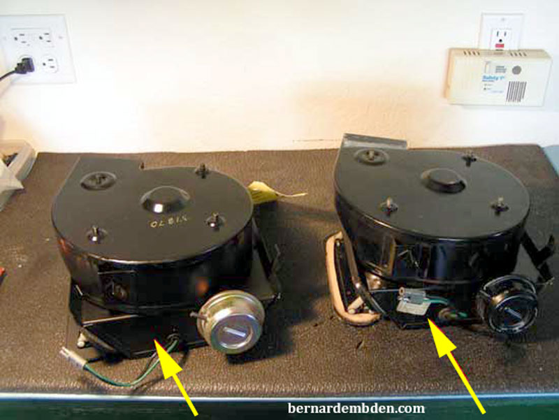
The rebuilt modules arrived from Coventry West. Photographed below are one rebuilt module on the left and the original module on the right. Note the rebuilt module has a new motor, new vacuum actuator, along with new door opening gasket and door flap seals. Inside the oblong, sleeve like compartment, (yellow arrows photograph below) the original plastic pins, metal rods and springs are reused.
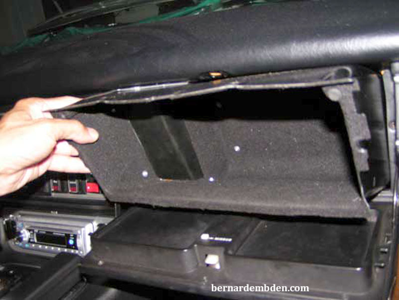
The project starts with replacing the right blower module. Remove the under scuttle and glove box.
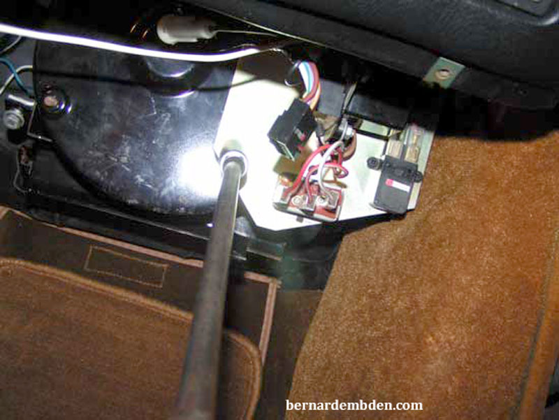
Remove two nuts securing a plate on which components, including the open door buzzer reminder, are mounted.
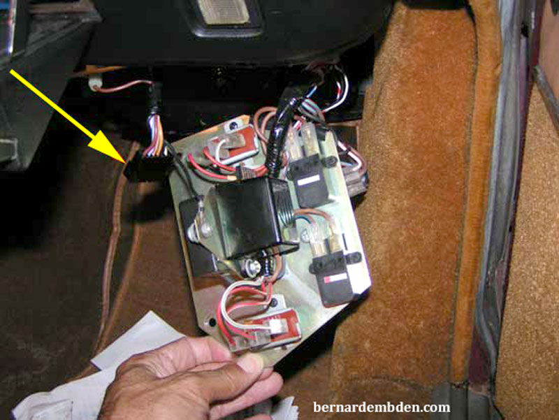
If the door open buzzer alarm annoys you, now is the time to unplug it. (yellow arrow photograph below). Secure plate away from work area.
Photographs below. Remove top and bottom nuts (yellow arrows) securing the blower module.
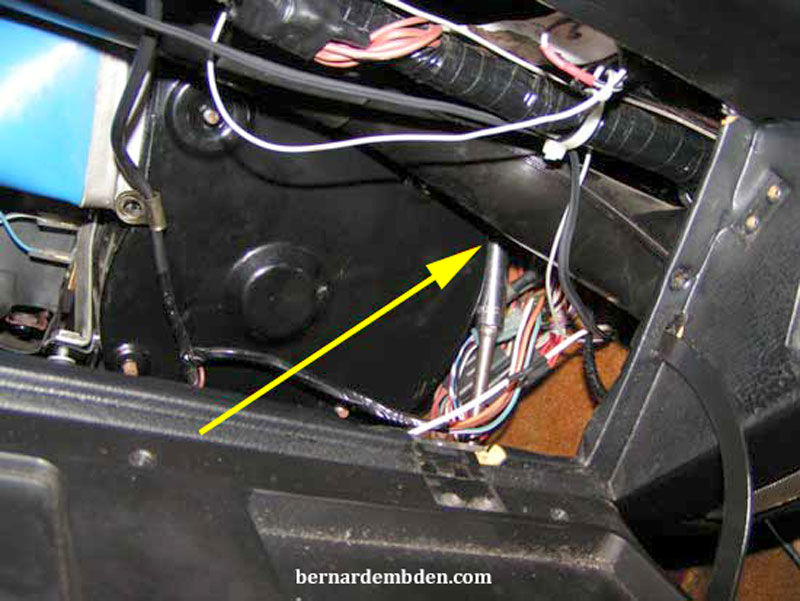
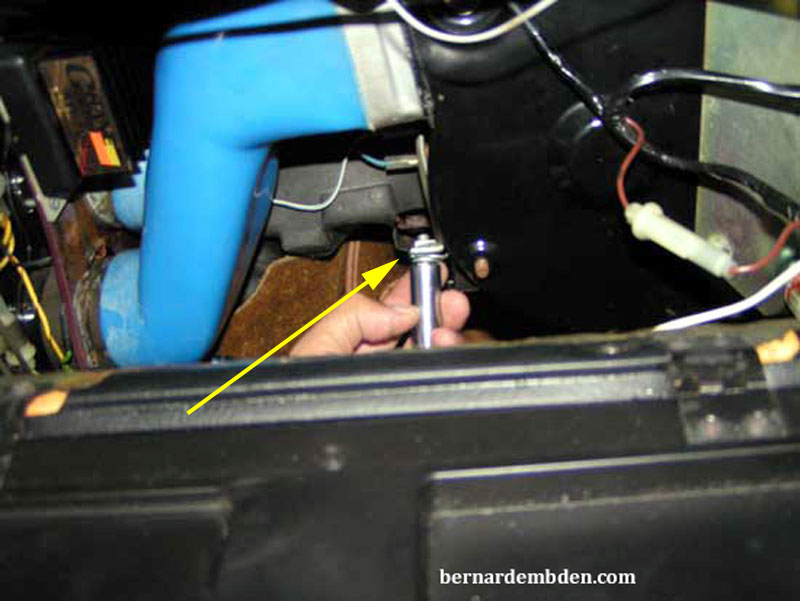
Remove the nut securing a wire harness clamp located across the top of the blower motor. Remove vacuum actuator hose, blower electrical connection and wires to the temperature sensor inside the blower sleeve compartment.
Wes Stewart indicates that on the later models there are two C-clips that attaches the large wiring harness to the blower unit. They are black vinyl covered and are difficult to see against the black electrical tape wrapped around the wiring harness. (These clips effectively hold the blower in place). One clip can be removed via a 10mm nut, the other must be bent to relieve the harness.
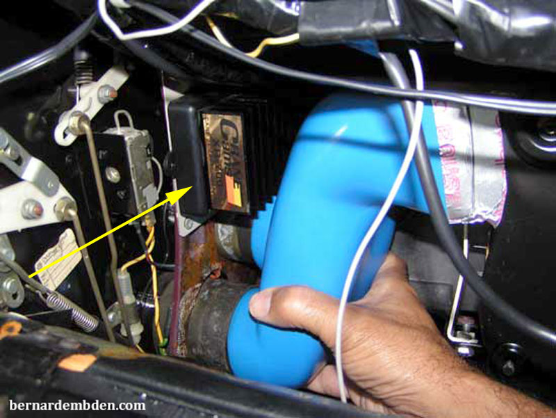
I also recommend removing the blue rubber duct from the old module (yellow arrow photograph below) I find it easier to maneuver the old unit out with this duct off.
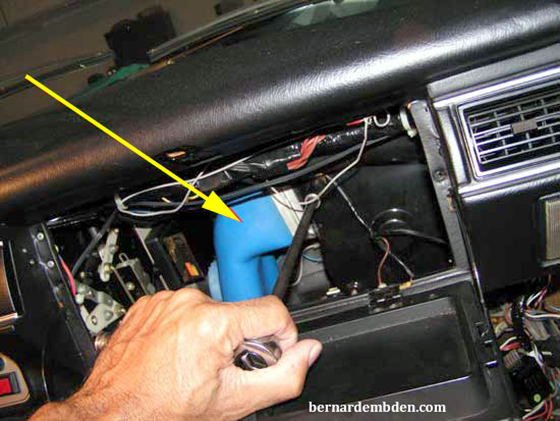
Take some time to observe the orientation of the blower module. Specifically, its relationship with the firewall and surrounding assemblies, along with the angle to the cowl. You will need to duplicate this when installing the rebuilt unit.
The top of the blower module's sleeve compartment, with the door flap, protrudes through an opening in the cowl at the top of the firewall. From this location the blower module sources outside air into the HVAC system. The normal position of the blower module is with this top door open. The problem is that the module cannot be removed from it's opening unless this top door is closed.
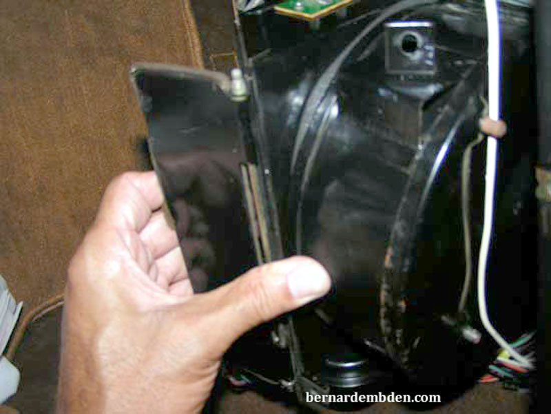
(Photograph below) Using one hand, open the bottom door. Linkages inside the module forces the top door closed. Note that the top door is at the top of the sleeve compartment, not the blower motor. To remove the unit you need to pull down, and slightly out, on the sleeve compartment while keeping the bottom door open.
It won't hurt to wiggly the component while pulling down and simultaneously repeating some type of prayer.
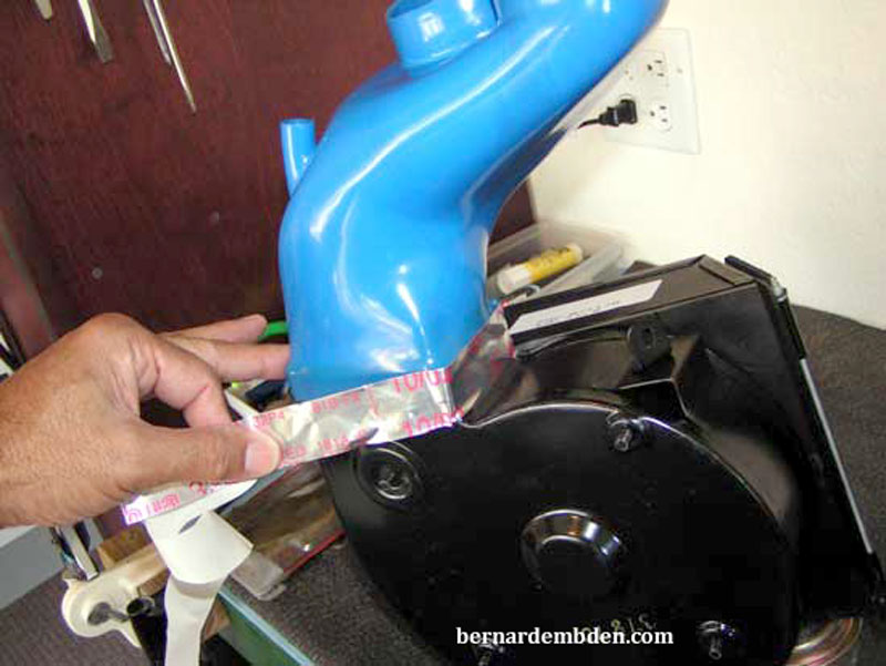
Once the old unit is out, clean the blue rubber duct and attach it to the rebuilt unit. It's important that you secure the duct with tape. I used a metal foil backed AC duct tape available from Home Depot or any decent hardware store. The hope was to tape the bottom of the duct and wiggle on the two top outlets.

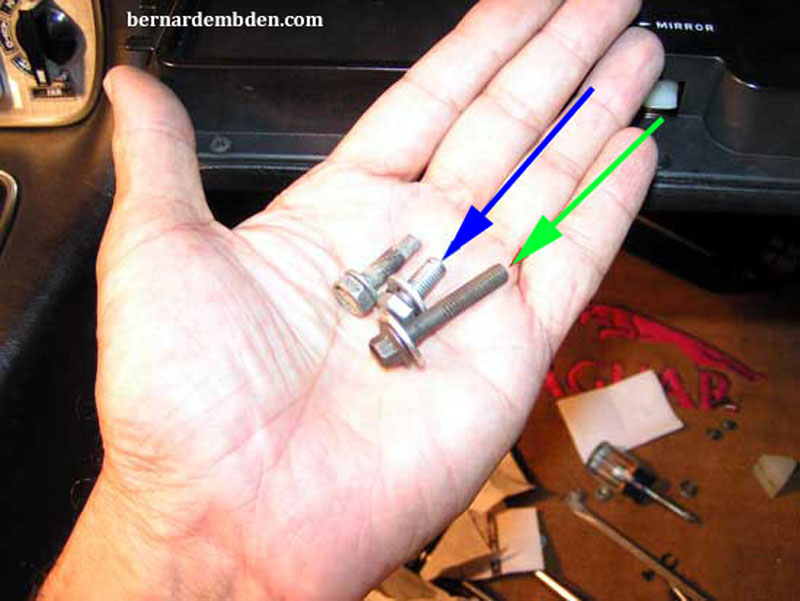
(Photograph below) Locate the original blower install bolts (blue arrow) and source a couple of bolts approximately 1 inch longer that the originals. (green arrow).
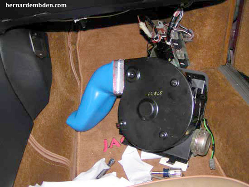
Offer up the rebuilt assembly (with the blue duct taped on) up to the firewall.
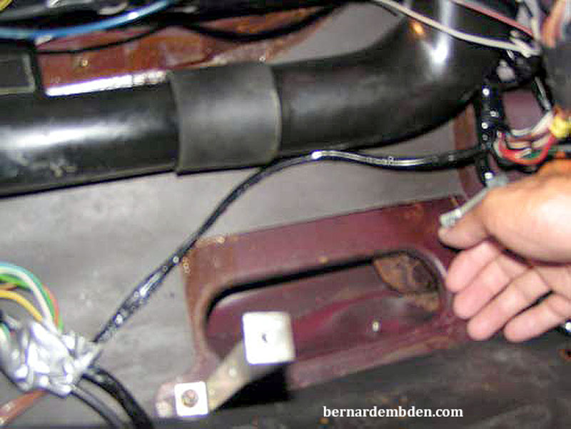
Photographed below is the opening in the cowl that the blower module's top door goes into. Note the position of my hand. This will allow me to guide the right side of the top door into the cowl opening.
Use your left hand (or a piece of wood) to hold the bottom door open while your right hand guides the top door into the cowl opening. With your right hand, position the right side top door into the cowl opening, then temporarily secure the blower module with the long screws sourced earlier. Do not tighten these screws. Attach the screws so the module hangs approx. 1 inch from the brackets. (yellow arrow photograph below).
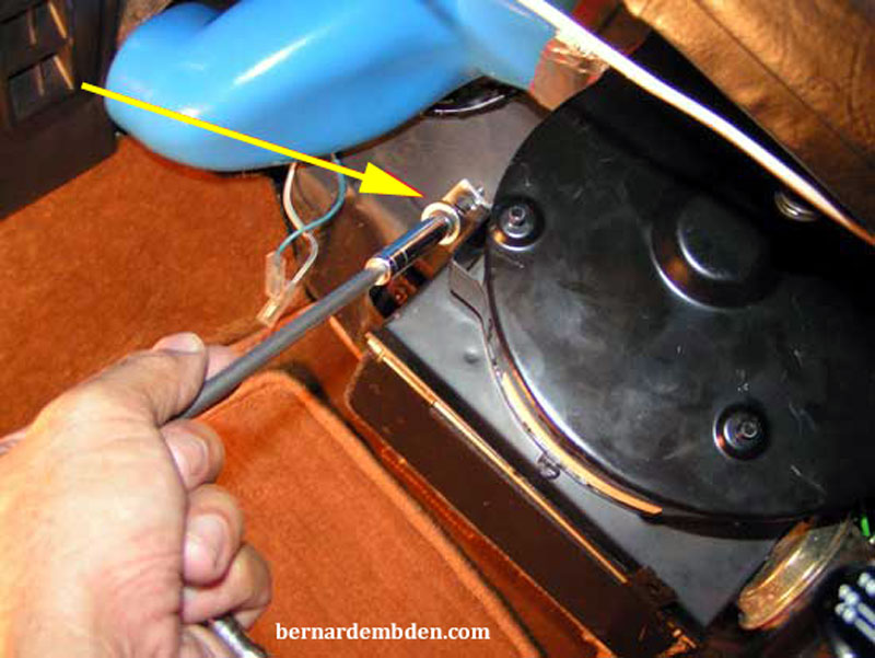
The long screws allow you to open the bottom door and wiggle the module in without having to hold it up. Remember the right side is already in. Push the door sleeve compartment (not the blower motor) up while keeping the module in the same orientation as when it was installed. (observed earlier prior to removing the module).
When the top door pops in, tighten both installations screws. Check the bottom door. It should be closed. It addition it must open and close without binding.
Doing only one screw at a time, remove the long screws and replace with the originals. Recheck module doors for binding.
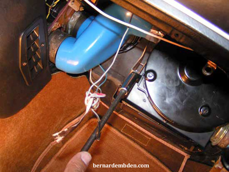
Attach blue rubber duct to HVAC matrix. I found it easier to attach both top and bottom ducts at the same time. In the photograph below, visible above the top duct is a Crane ignition amplifier. (yellow arrow photograph below). This project is covered under another link in this website.
Connect vacuum actuator hose, temperature sensor wires and blower motor connection. Replace component plate and wire clamp to blower assembly. Install glove box and under scuttle.


Suggest you have a drink before moving to the left side.
Start by removing the left side (drivers side US) under scuttle. Remove and tag wires for the dashboard dimmer. (blue arrows)
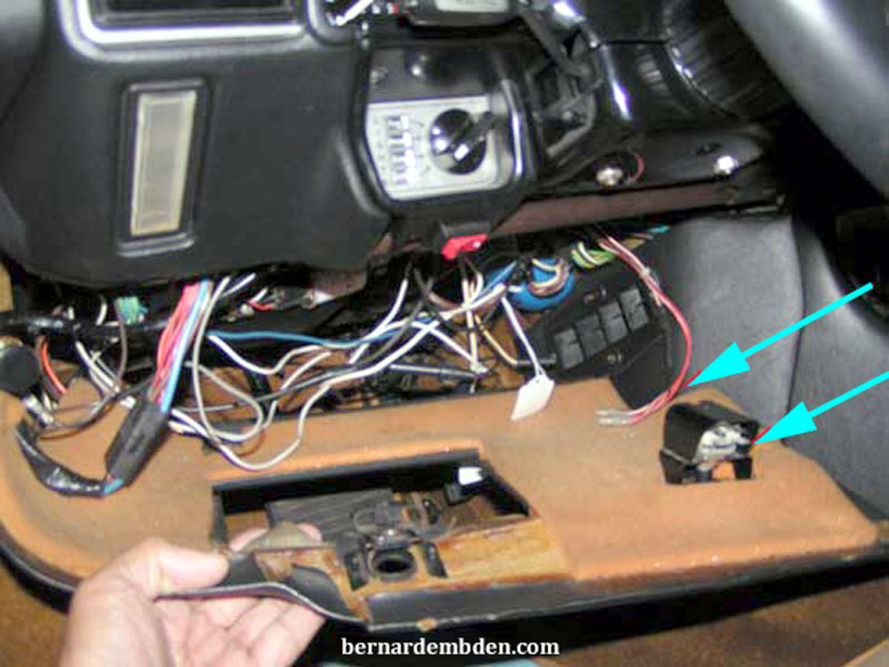
(Photographs below) Remove dashboard. I also removed the steering column to cowl support. Although this was not completely necessary, it gave me better visibility and access.
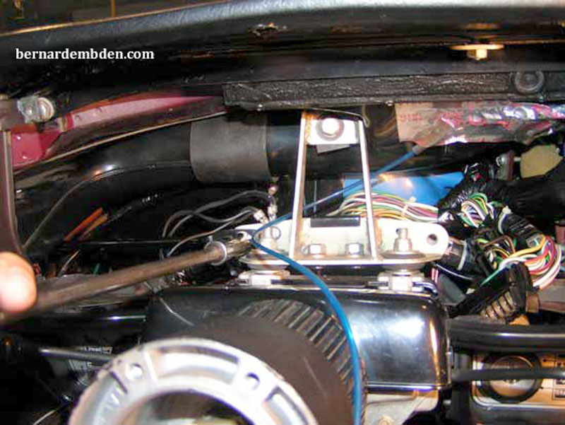
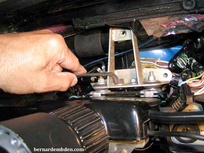
Remove three screws that secure the fuse box mounting plate, hazard/blinker and relay. Remove the vacuum actuator hose and blower electrical connection.
Remove "T" connection pipe from the blue duct. (red arrow photograph below). This specially made T pipe uses the venturi effect to create a small vacuum as the left blower motor pushes air through it. This vacuum pulls air across a sensor mounted behind the glove compartment. This sensor determines the in-cabin temperature, information needed by the automatic HVAC system.
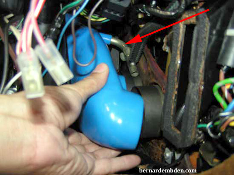
Prior to maneuvering the old assembly out I completely removed the blue duct from the old blower module.
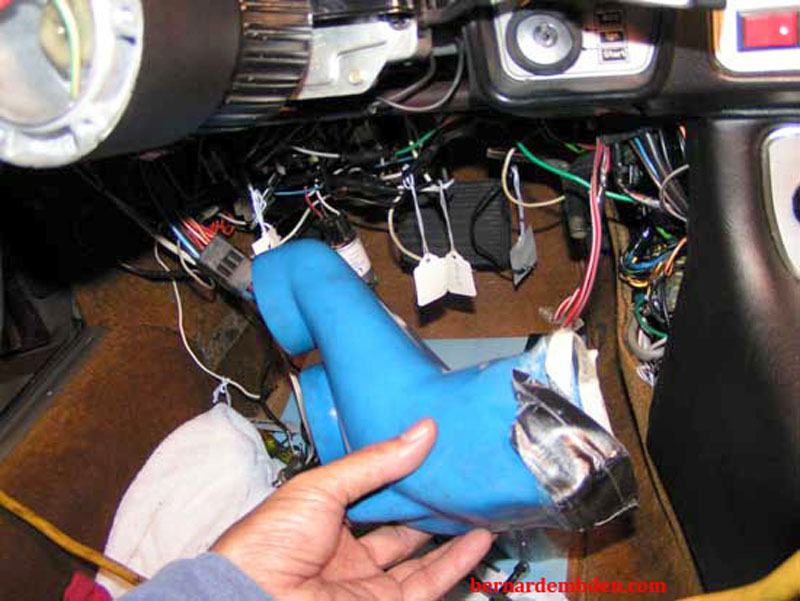
(Photographs below) Remove two bolts holding the blower module. (yellow arrows) Note the fuse box removed from its mounting plate. (green arrow) This is in preparation for the next project, replacing the fuse box.


You know the drill. (with the mounting bolts removed) while keeping the bottom door open, withdraw the blower assembly straight down from the cowl opening.

Clean the blue rubber duct and attach to the left side rebuilt module.
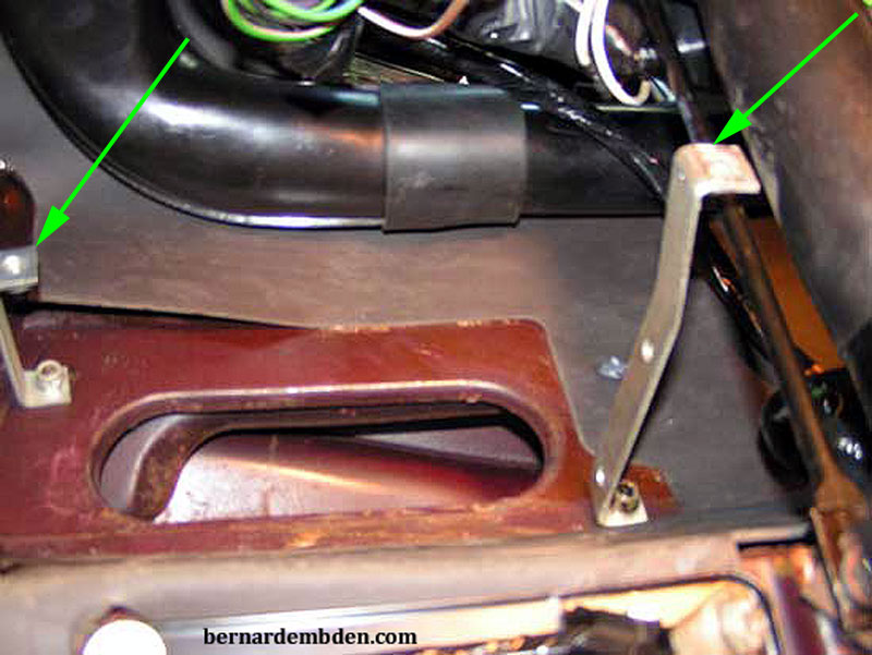
Photographed below is the opening to the cowl that the left blower module goes into. Note mounting straps. (green arrows).
With the blue duct properly attached and taped to the rebuilt module, offer the assembly from underneath, duct first, over the steering column.
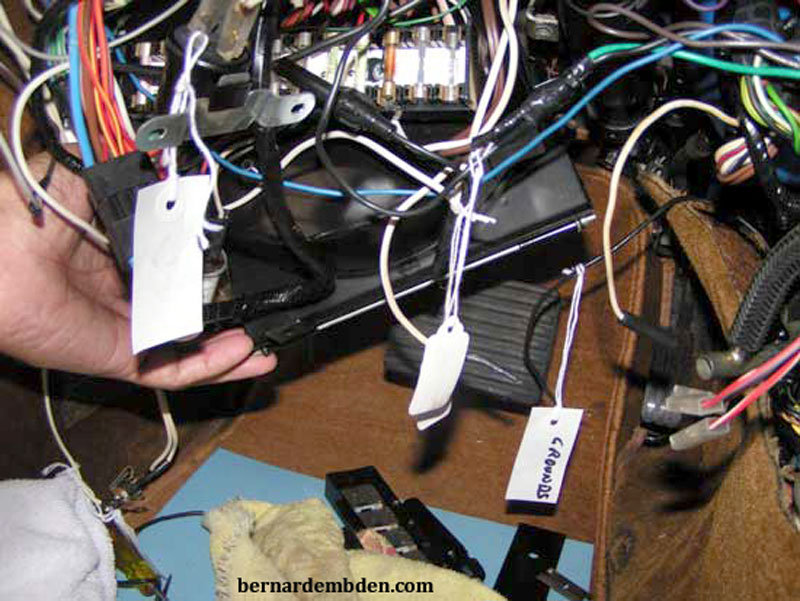
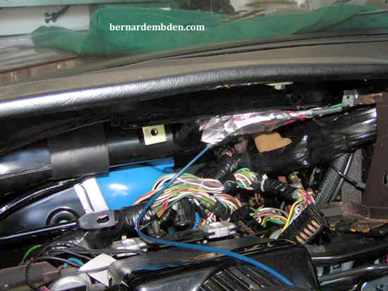
Using the same technique as the right side, Use your right hand to keep the bottom door open while your left hand guides the left side of the top door into the cowl opening. Once the left side is in, use the long screws to hold the assembly in place. Holding the assembly in the orientation that it came out, keep the bottom door open while you wiggle it in. Remember, the left side is already in. Work on the right side. Once in, tighten the long screws and check the operation of the doors. Replace the long screws and re-check the doors for binding.
Attach "T" air monitor pipe to the blue rubber duct. Connect the blue duct to the two openings in the HVAC matrix. Connect the vacuum actuator hose and blower electrical connections. Replace fuse box mounting plate.
Reinstall steering column support and dashboard.

This is not a difficult project. This is a pain in the ass project.
