
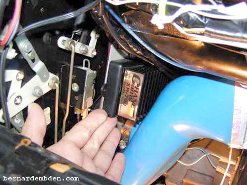
Not only is the original "OPUS" Lucas ignition amplifier junk, its location defies logic. It's installed on the engine in the middle of the engine "V" where the engine temperature is at its worst. This amplifier was later redesigned by Jaguar with longer leads so the location could be moved off the engine, but these amplifiers continue to fail. After replacing the original and redesigned Jaguar amplifiers I decided that the permanent solution was to install an aftermarket unit manufactured by Allison. (Allison was later acquired by the electronic division of Crane Cams).
Note that the Allison/Crane ignition amplifier was also designed to be installed inside the engine compartment, albeit not directly on the engine itself. This seemed like a recipe for disaster. Very few, if any, engine compartments get as brutally hot as the Jaguar V-12. My solution,
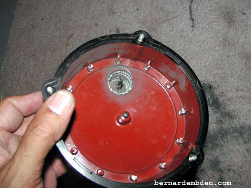
Mount the ignition amplifier inside the car!
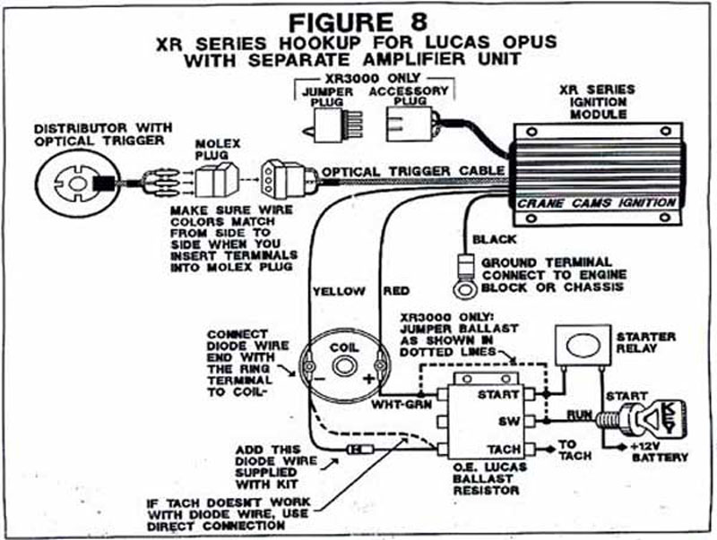
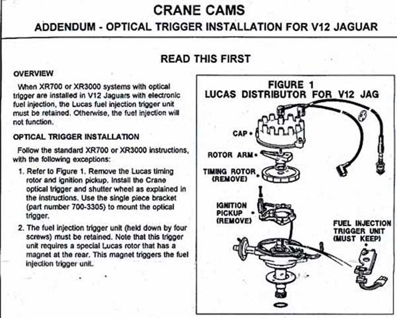
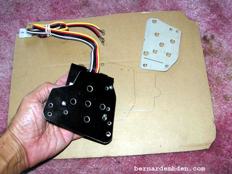
I chose the Crane XR700. The schematics (photographed below,) detail the installation. (Note the addendum. The trigger unit must be maintained. ) There is also a diode supplied that may or may not be necessary to have the tachometer operate properly. This will be addressed later.
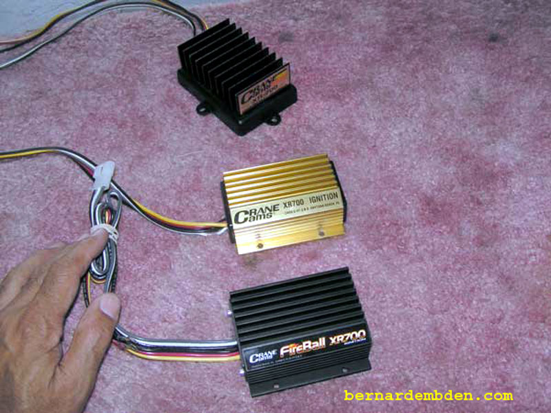
Pictured below are three generations of Crane amplifiers. The top unit was purchased over 20 years ago and is the subject of this project. The middle unit is somewhat newer and was purchased as a spare. It was never used. The lower unit (FireBall XR700) is Crane's latest model. (Year 2009).
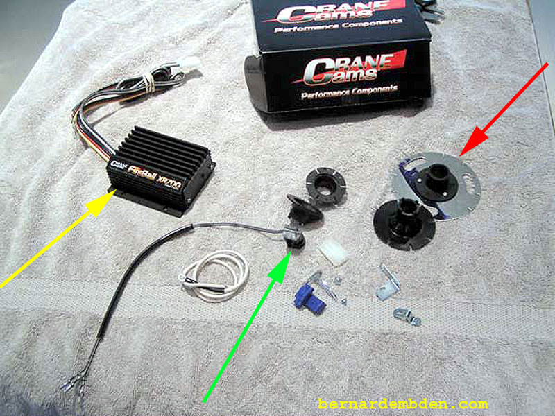
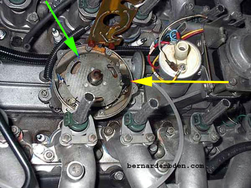
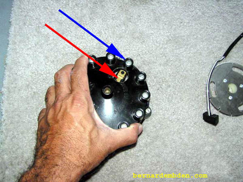
Photograph below. The Crane unit comes with a bewildering amount of small pieces and brackets. The main parts are :
The amplifier (yellow arrow).
The trigger unit (green arrow)
The shutter wheel designed specifically for the V-12 engine. (red arrow).
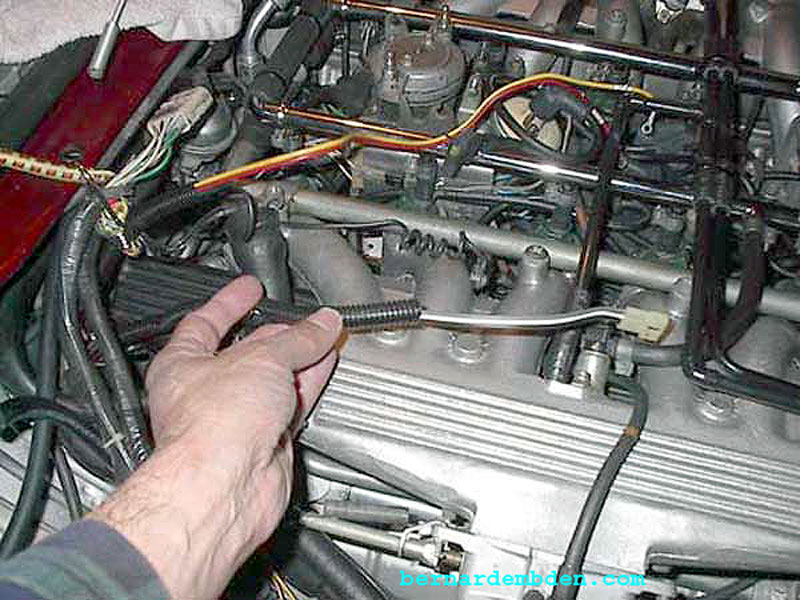
The project starts by checking the timing on the V-12 engine. For the Pre-HE V-12 engine the timing is 10 degrees BTDC at a maximum of 900 RPM with the distributor vacuum advance module disconnected.
Do that now.
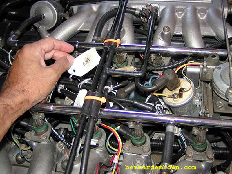
Remove the distributor cap. I strongly recommend labeling the spark plug wires unless you enjoy extra work. Now is a good time to check the mechanical and vacuum advance mechanisms. These mechanisms are prone to seizure.
If the mechanical advance is seized or otherwise inoperative, correct the problem, re-install the distributor cap and re-check the timing. It's critical that you get this right.
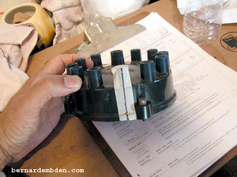
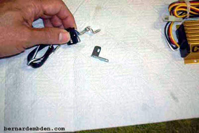
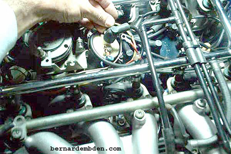
Once the correct timing has been established, remove the distributor cap and mark it at the number one spark plug wire location. (photograph below).
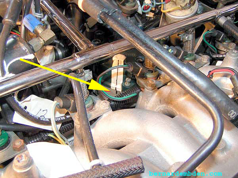
Re-install the marked distributor cap and using the mark on the cap as a guide, draw a line onto the distributor housing at the number one spark plug wire location. (yellow arrow photograph below).
Remove cap and rotor. Remove the 4 plastic screws retaining the Fuel Injection trigger unit and swing away from the distributor housing. Remove original "Electronic timing rotor" and pickup module. Retain plastic screws, they are almost impossible to source.
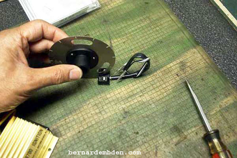
The shutter wheel and optical trigger unit (pictured below) replaces the original electronic timing rotor and pick up module.
The Crane kit comes with a set of adjustable brackets to mount the optical trigger to the "Electronic module mounting bracket's pick up arm". (Note: The vacuum advance operating rod and distributor pick up module attaches to this pick up arm)
These brackets are crap.
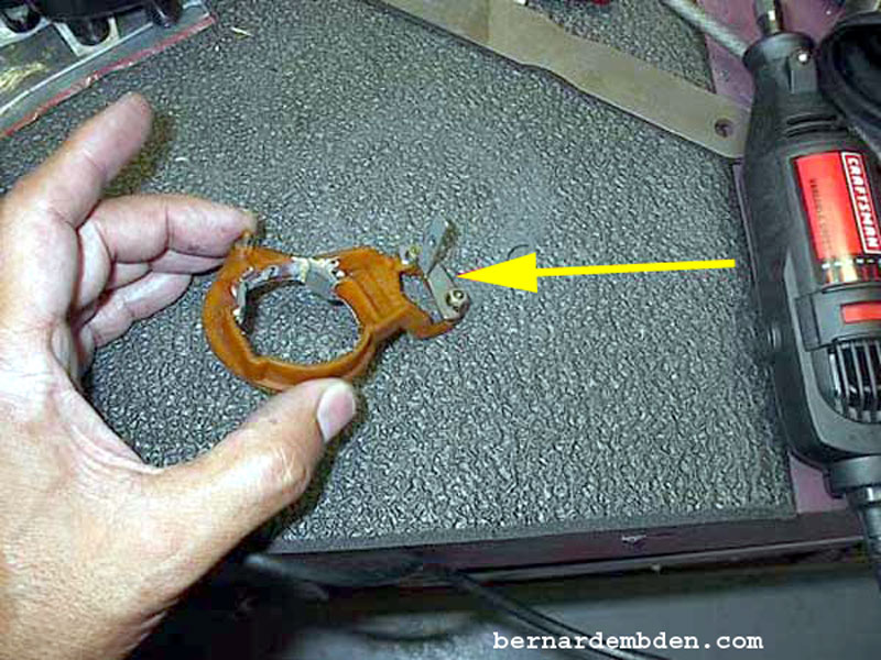
You might want to use them to determine the preliminary position of the optical trigger. After that, spend some time fabricating a proper bracket to hold the optical trigger. I fabricated a bracket from sheet-metal stock that met my requirements (yellow arrow below). Determine preliminary position of the bracket by temporarily mounting the optical trigger and shutter wheel. Suggest you design some adjustability in the bracket, you will need it.
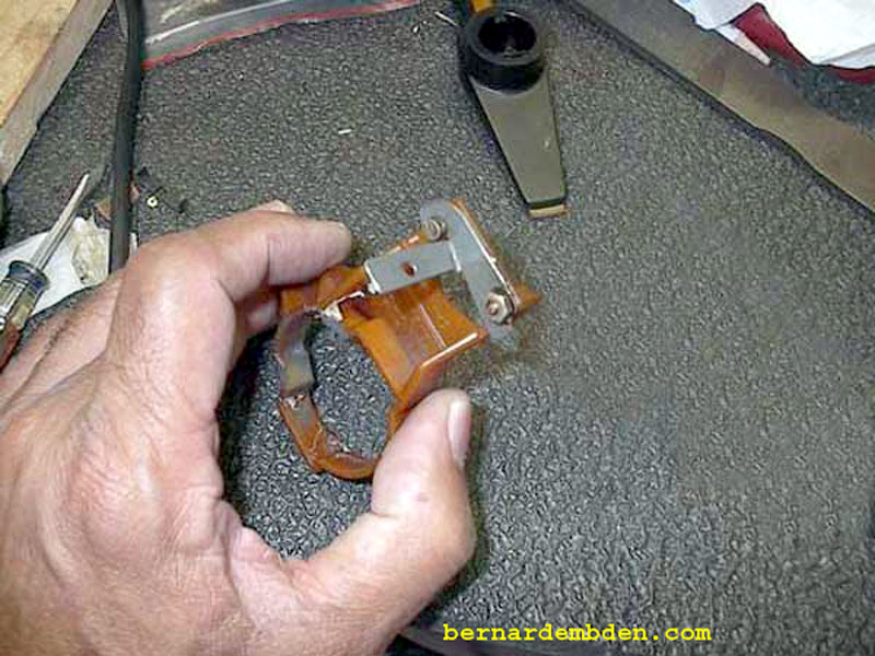
Photographed below is the final bracket design.
Once the bracket is fabricated, using high temperature grease, lightly grease and install the pick-up arm and the arm spring. Install the shutter wheel, washer and circle clip. (green arrow photographed below).
Install the optical trigger. Temporarily connect the Crane amplifier to the optical trigger and ignition coil.
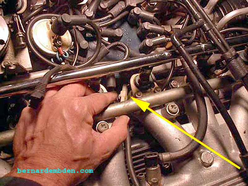
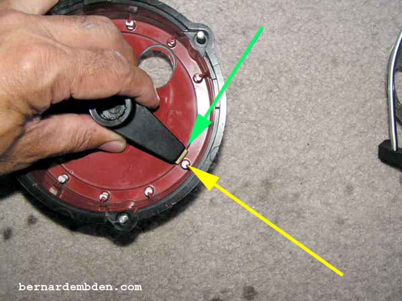
Photograph below. Static time the optical trigger by observing the leading edge of the shutter wheel (green arrow) just entering the optical eye of the trigger (yellow arrow) as the rotor points directly at the mark on the distributor housing. (photograph below, rotor removed for clarity.)
The optical trigger has to be mounted (and adjusted) so that when the leading edge of the shutter window reaches the optical trigger the rotor is pointing directly at a spark plug terminal, in this case the mark on the distributor housing.
The original timing rotor, with its buried ferrite rods and pick up module, is discarded. They are replaced with the 12-window shutter wheel and optical trigger. The stock distributor cap, rotor and fuel injection trigger unit is retained.
Note: On the current Crane amplifiers a light indicates when the amplifier executes. This can be used to static time the optical trigger.
Get this right, the successful completion of the project depends on it.
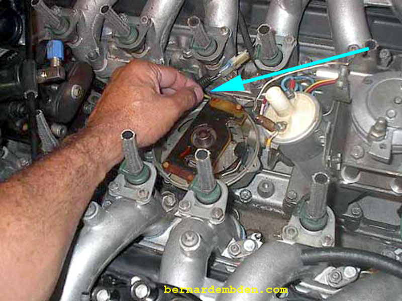
Once you have static timed the optical trigger with the shutter wheel and distributor cap plug wire location, re-install the original Fuel Injection Trigger Unit with the four plastic screws. (blue arrow photograph below).
Install rotor. Note position of installed optical trigger (blue arrow).

I used a generic plug and high temperature silicone sealant to augment sealing where the wires from the optical trigger passed through the distributor housing. (green arrow photograph below.) Note that the Crane unit comes without a replacement plug).
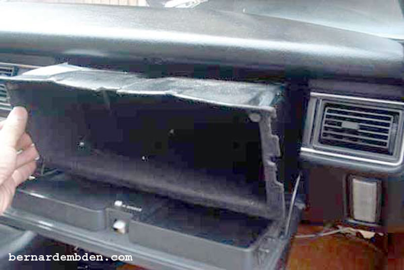
This project was always to install the amplifier inside the car, away from the hostile environment of the engine compartment. To accomplish this the glove box had to be removed.
You will need to fabricate a bracket that the Carne Amplifier will mount to. The photograph below shows brackets for the original and new Crane amplifiers.
Put you big boy pants on. Disconnect the battery. Using a one-inch drill bit, drill a hole from inside the car through the firewall. The hole must be large enough to pass the plastic plug through. If necessary, you can use a smaller bit and massage the opening with a round file.
Great care must be exercised here. The object is to exit just below the 12-volt rod that runs across the firewall. If necessary, drill a small pilot hole first.
Measure carefully, therapy awaits you if you screw this up.
Pass the amplifier wire leads through the hole in the firewall. Install bracket and amplifier onto the heater/AC side support. The bracket is necessary because the available amplifier mounting holes do not line up with anything on the AC side support.
The amplifier wire length is critical. It determines the final location of the amplifier inside the car. Also note the red and yellow wires. They will be connected to the coil.
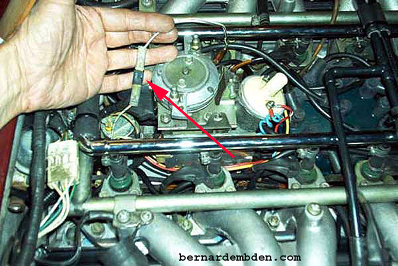
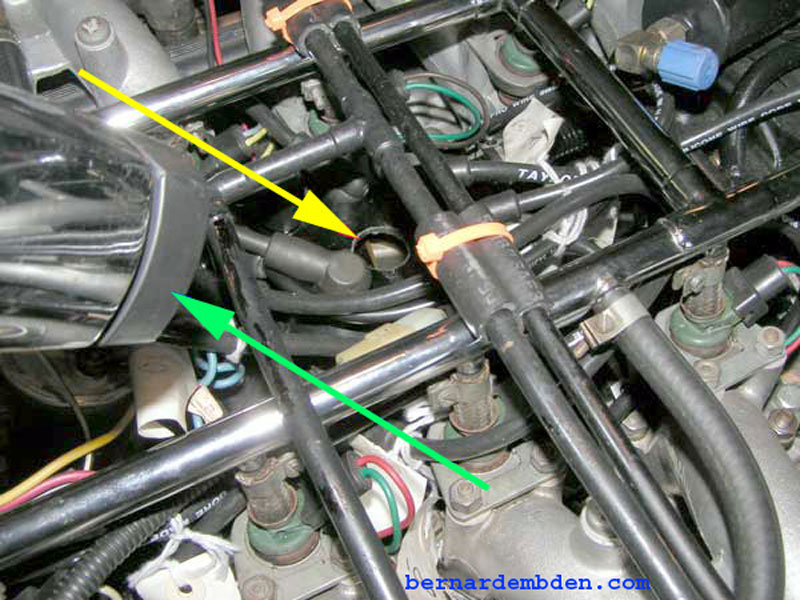
Route the amplifier wires beneath the intake manifold. This represents the shortest distance to the distributor. Connect the amplifier plug to the optical trigger plug from the distributor. (yellow arrow photograph below).
The glove box will fit without modification, however it rests against the amplifier. I wanted a minimum of 2 inches clearance around the amplifier, and the ability to remove the amplifier without removing the glove box. To accomplish these goals I modified the glove box as per the photograph below.
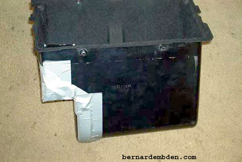
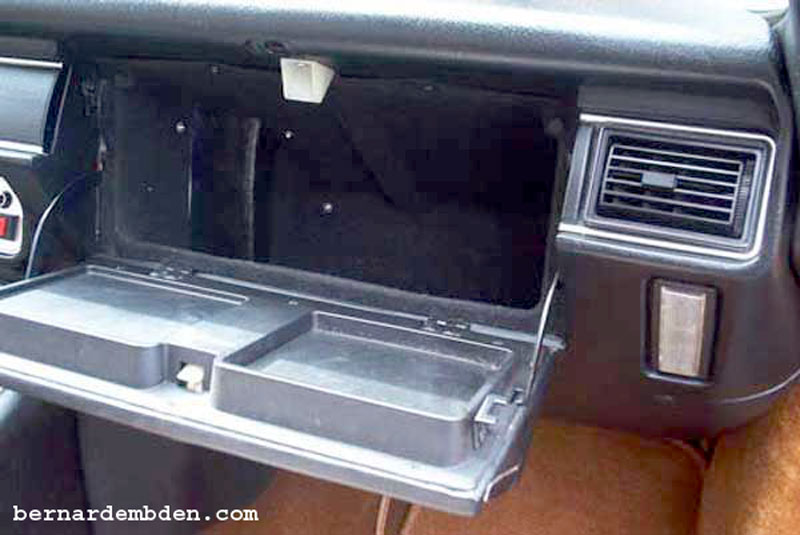
Glove box installed. I covered the modification with leather to match the inside of the glove box compartment.
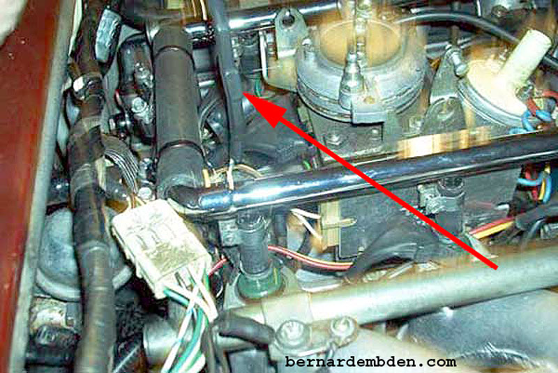
The tachometer requires a diode to be installed in the sensing wire. (Crane used to supply this diode.) Once connected I used a large heat shrink tube to secure the connection. (red arrows photograph below).
From the amplifier, connect the red and yellow wires to the coil (observe polarity) and the black wire to ground.
For most people, the project is completed.
Start the car, drive safe.
However there are variables that should be accounted for, essentially the mechanical and vacuum advances. The car is designed to run optimality at 10 degrees BTDC.
The optical trigger unit was static timed at 10 degrees BTDC with the engine off. There is no provision on the static timing for the centrifugal advance variable.
I needed to see the rotor's position with the engine running.
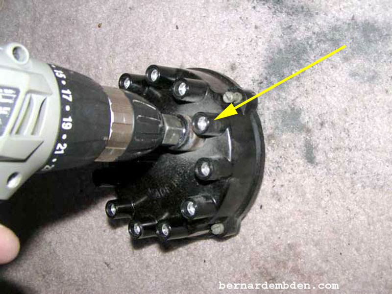
Source a spare distributor cap. Or purchase one from local discount auto store or a mail order store. (In my case I used a perfectly good distributor cap). Drill a one-inch hole in the distributor cap directly opposite the number one spark plug's distributor wire. (yellow arrow photograph below).
(Photograph below) The objective is to adjust the optical trigger so it is fires the coil when the rotor (red arrow) is pointing exactly to the number one plug wire on the distributor cap. (blue arrow) with the engine running.
As the photograph below shows, if timed correctly, then the width of the rotor (green arrow) passing by the distributor caps contact (yellow arrow) is enough to handle the added rotor movement resulting from timing advancement initiated by the vacuum advance module.
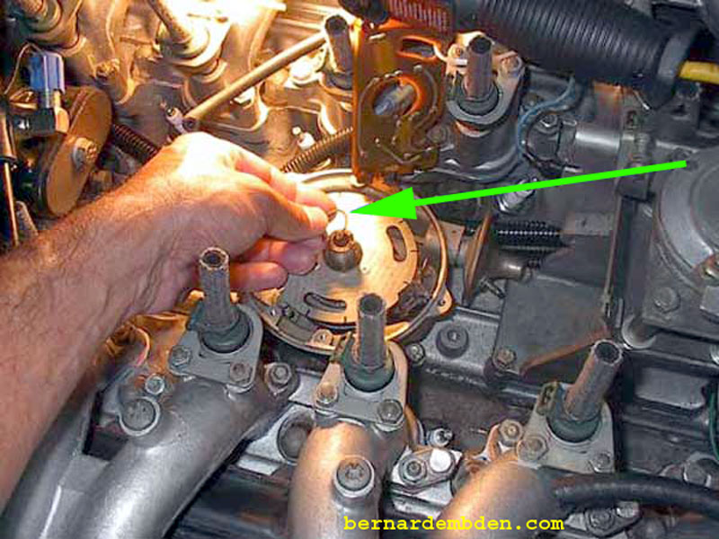
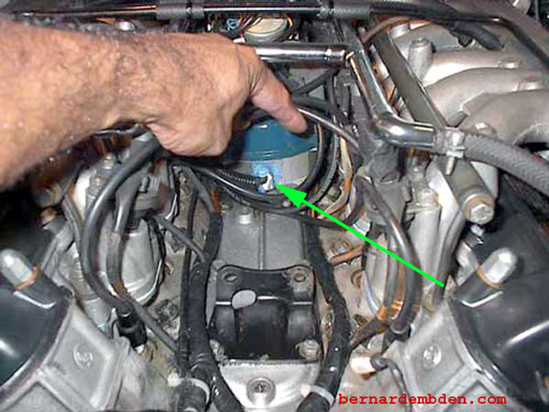
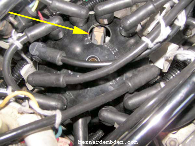
Install modified distributor cap and start engine. Timing should be at 10 degrees BTDC. Maximum 900 RPM. Vacuum advance disconnected. Connect timing light (green arrow photograph below) to number one spark plug lead and, using the timing light pulse, observe position of rotor at the hole at the number one plug position of the distributor cap. (yellow arrow).
With the engine at 900 RPM and the vacuum advance module disconnected, the rotor should be pointing Exactly at the number one plug wire on the distributor cap. (yellow arrow photograph below) Adjust optical trigger if necessary.
If the above is correct, Replace modified (hole drilled) distributer cap. Re-connect distributer vacuum advance module.
Project complete. Take your time on this. If you want the car to run properly, there is only one way to do this project.
The right way.
