
The Jaguar XJS has two primary fuse boxes. The smaller of the two, located inside the engine compartment on the left fender panel, was replaced some time ago.
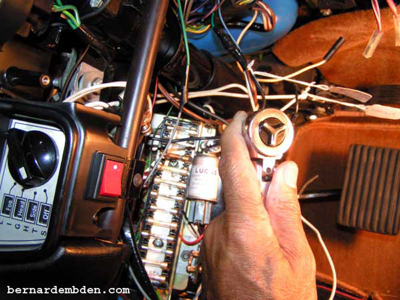
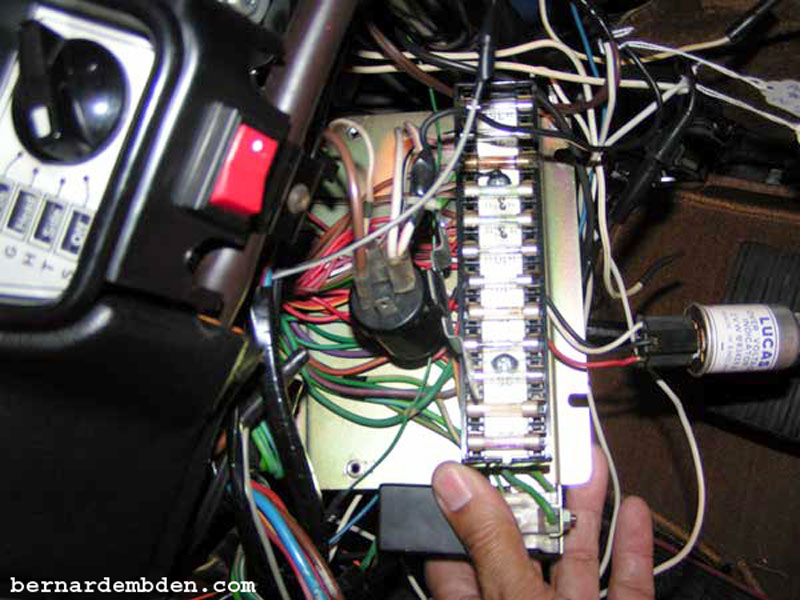
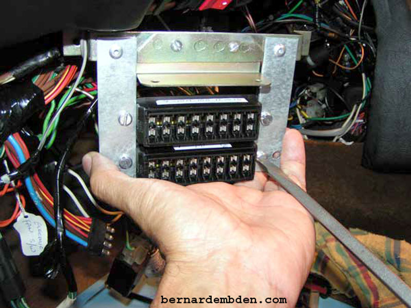
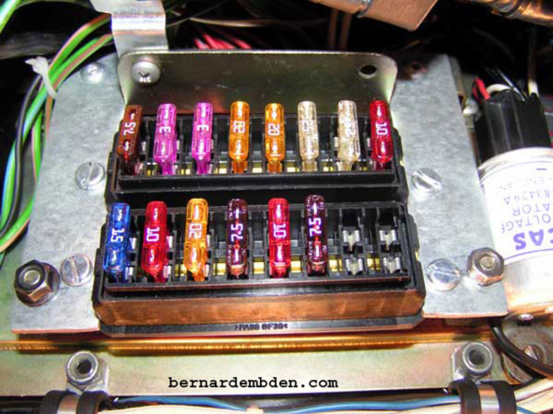
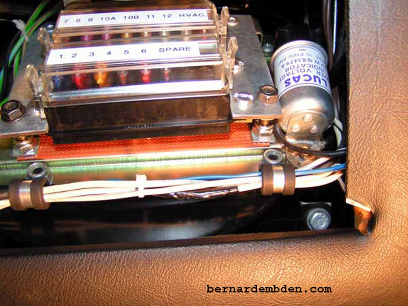
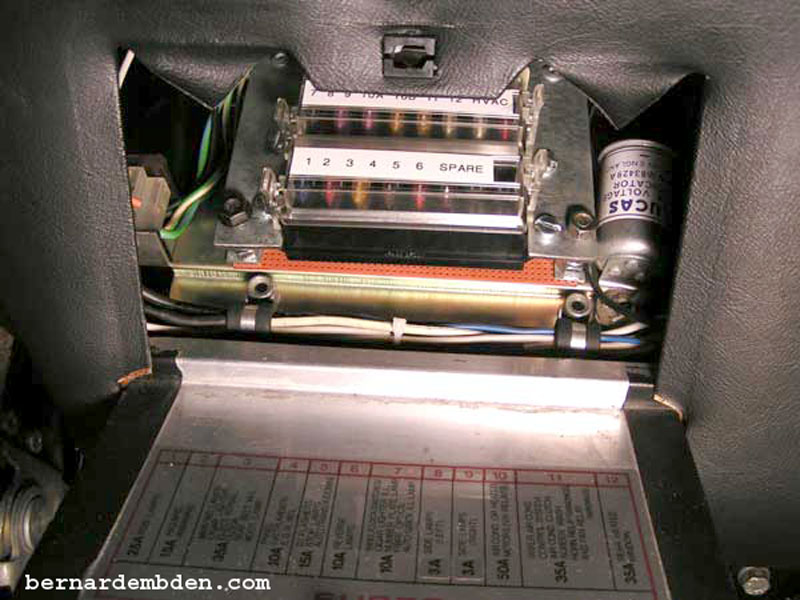
The main fuse box is bolted to the left blower motor, located underneath the scuttle on the left side of the dashboard. This fuse box contains 12 Lucas barrel type glass fuses.
The problem with the main fuse box is not that its 30 years old, or that it does not gang same source wires to single contacts, or that it uses the old, obsolete round glass fuses.
The problem with the main fuse box is that it was designed to have fuse number 10 burn the car to the ground.
Jaguar has inexplicitly designed this fuse panel with single wires to fuse numbers 8 and 9 carrying 3 amps each, while routing two power feed wires to fuse number 10 and requiring it to carry 50 amps.
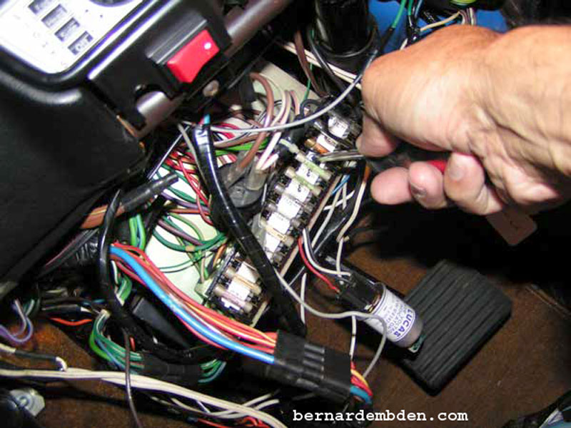
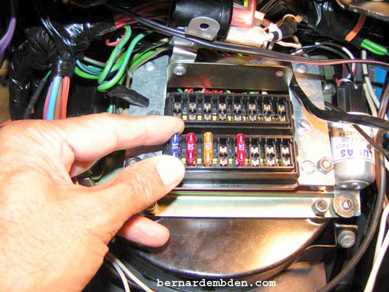
Over the years, no doubt aided by increased resistance between the glass fuse and it's contacts, heat generated at this fuse has actually melted the plastic fuse box on virtually every Jaguar XJS, as photographed below.
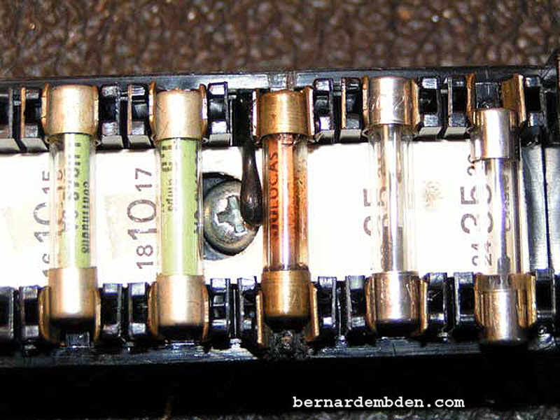
I have no idea at what temperature this plastic fuse box melts, but I do know that kind of heat should not be anywhere close to me.
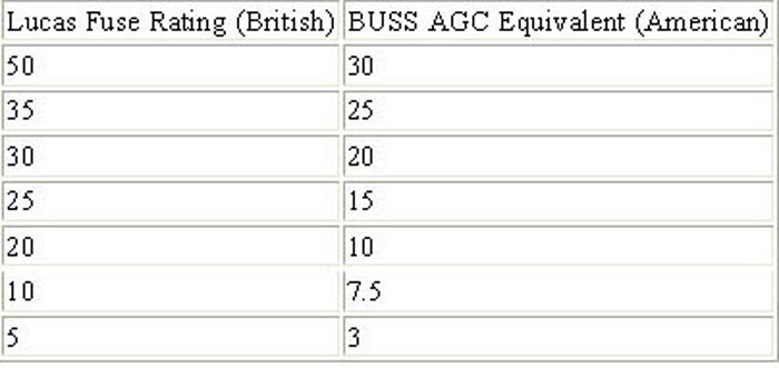
Further complicating this issue is the fact that although the fuses might look the same, and they might be labeled the same, these amperage ratings are British Standard and differs significantly from the current AGC American (and international) standard.
Example. The Lucas 50 amp fuse is designed to blow at 50 amps. The wiring it protects is designed to operate at a lower voltage (approximately 30 amps.) At 50 amps this wiring is above its designed limit, and cannot tolerate this additional amperage.
The AGC American fuse is designed to run at 50 amps. The wiring it protects is designed to operate continuously at 50 amps. This fuse will not blow until amperage reaches the 60 to 70 amp range.
What this means is that replacing a Lucas fuse with an AGC fuse with the same amperage rating is akin to Russian roulette. If there is a problem in the fuse-protected circuit, the fuse will not blow at the limit that the British wiring system was designed for.
At this point a good fire extinguisher will be required.
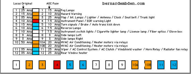
The differences are readily apparent in a chart photographed below allegedly sourced from a vintage British car owner’s manual.
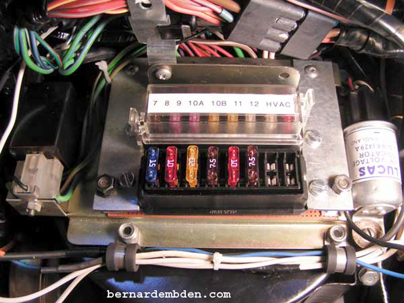
Before starting this project I wanted to know exactly what circuits in the fuse box were powered, which fuse contact the power came from and when they became powered. Using a voltmeter I tested each fuse under ignition off, accessory and engine running conditions. The results are detailed in the chart below.
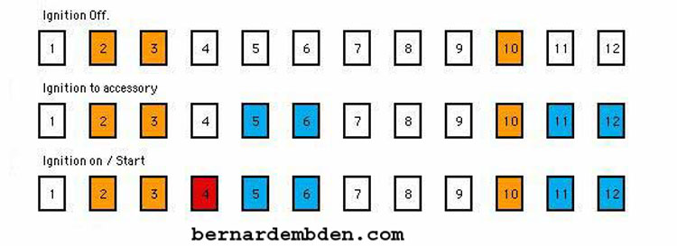
Ignition off, Fuses 2, 3, and 10 shows 12 volts. Ignition to accessory, additional fuses 5, 6, 11 and 12 show 12 volts. Finally, with the car running, fuse number 4 now shows 12 volts. Fuses 1, 7, 8 and 9 have switched current. (Current after a switch has been turned on). In addition, with the exception of one fuse, all the power enters the fuse box at the top fuse connections.
At this point you might be thinking, why not use a current, modern style fuse panel that gangs same source feeds together? Fuses number 2, 3, and 10 could be one contact in, "Accessory on" would be fuses 5, 6, 11, and 12 etc.?
The fact that you own one of these cars means that you enjoy some pain, however in this case my recommendation is to forget about it. It's just not worth the trouble.
There are two ways to replace this fuse box.
1) The easy way.
Purchase a number of fuse blocks with wires designed for single ATO fuses and enough to total 12 fuses. Connect the existing fuse wiring to each fuse block. Mount somewhere convenient. You are done, drive safe.
2) The hard way.
Replace the existing fuse box with an entirely new ATO fuse panel. Mount in the same location. Connect or solder the existing wires directly to the new fuse panel, split fuse number 10 into two fuse circuits.
You know I will be doing this the hard way. A new fuse panel will replace the fuse box while keeping the existing wiring, with the exception of fuse number 10.
The fabrication of this fuse panel is detailed on another link of this website.
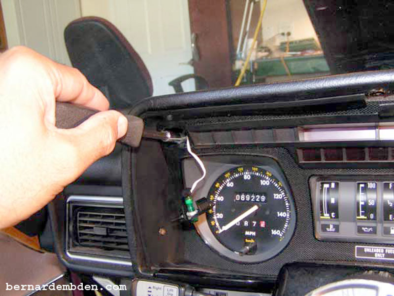
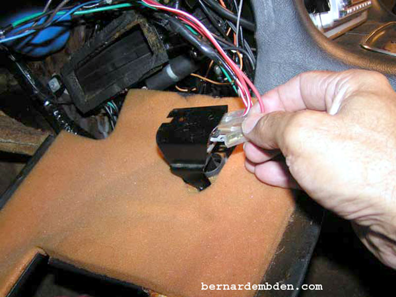
This project starts with removal of the left side under scuttle. In addition, I recommend removal of the dashboard. While not completely necessary, this step will make your life easier.
Remove four screws that attach the fuse box mounting plate to the left blower motor. Pull the mounting plate down and remove the ignition relay mounted on the top bracket of the fuse panel.
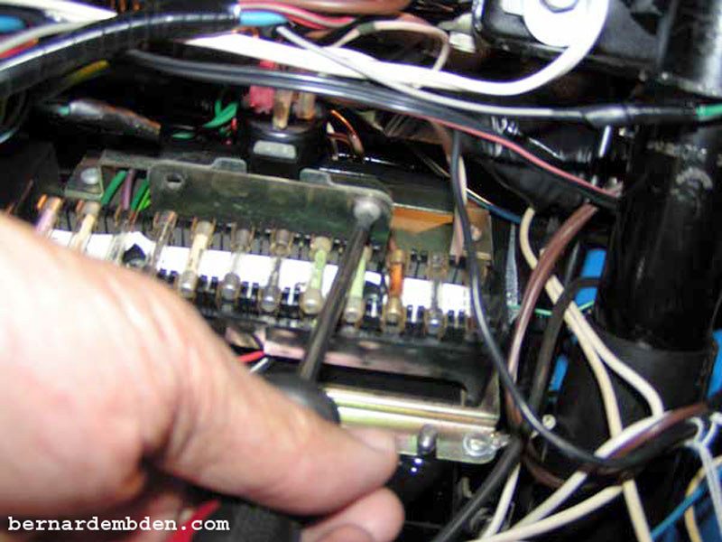
Remove voltage regulator and hazard flasher unit.
Using a Phillips screwdriver remove the two screws securing the fuse block to its mounting plate.
At this point you have already fabricated a new fuse panel haven't you? You will need it.
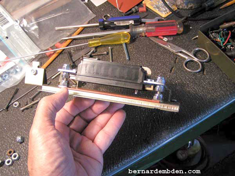
(Photograph below) The new fuse panel used 1/4-inch blade type connections at the bottom of the blocks. I was determined to keep the fuse blocks the same height as the top bracket, approximately 1/2 inch above the mounting plate. Conventionally crimping the wires to a female spade connector, and connecting it underneath the fuse block would force the top of the un-insulated wire connector to bend as the fuse panel was bolted down to the mounting plate. It was important that only the insulated wire would bend as it exits the bottom of the fuse blocks.
Another methodology was needed. I decided to connect and solder the wires to the side of the connector. This would allow the exposed, soldered connection be mostly inside the bottom of the fuse box. Only the insulated wires would have to bend as they exit underneath the boxes.
This would require some modification to the method used to join the wires to the female 1/4 inch connectors. Each female spade connector would have to be modified. Start by opening the crimp end using needle nose pliers. (green arrows photograph below).
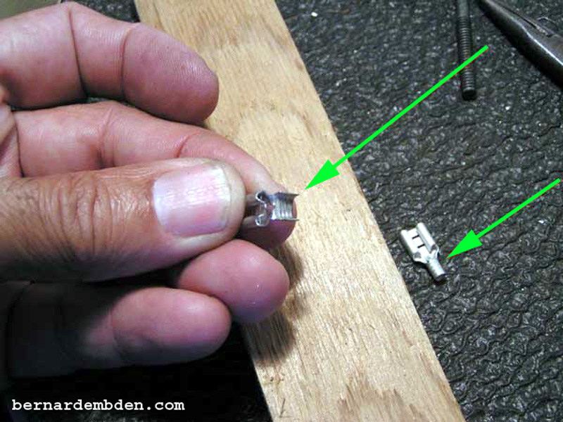
Remove the curve from the connector tip and bend it 180 degrees until it is in contact with the side of the connector. Re-curve the connector tip to accept the wire as photographed below.
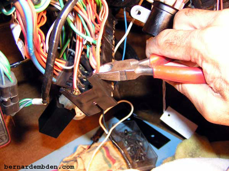
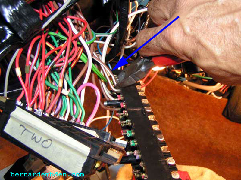
Turn the existing fuse box upside down and identify the number one fuse. Cut the wire close to the fuse box connection. (at this point there is no turning back. Don't be scared you can do this).
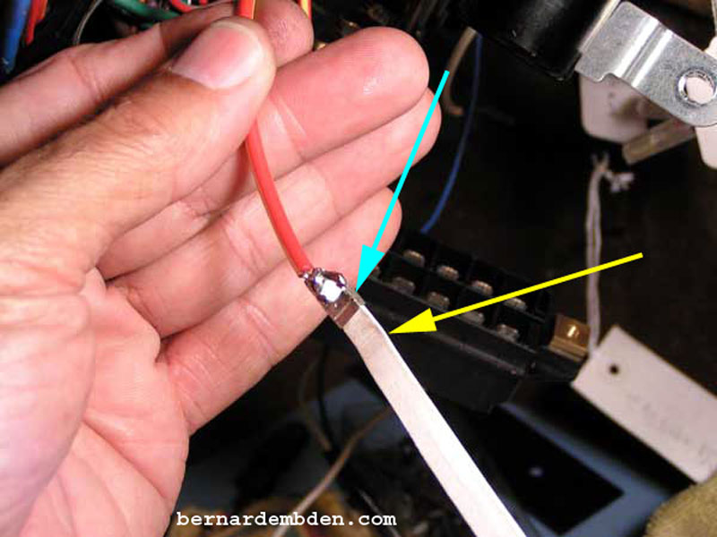
Clean and attach the cut wire into the modified spade connector tip. Crimp to hold the wire in place. Fold a business card and cut to size that allows you to insert the folded cut end (yellow arrow photograph below) into the spade connector channel. (light blue arrow).
This step is important. It keeps the spade connection channel free of solder. Without this step the spade channel will fill up with solder rendering it useless. It will not push on to the new fuse box's male connection.
Solder the connection. Good soldering practices must be followed. The connections must be cleaned and liberal use of flux is encouraged. The objective is to solder the connection onto the side of the spade connector as seen in the photograph below.
Once soldered, push firmly and connect to the number one fuse of the new fuse box.

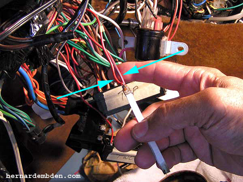
Use the same technique on double wires. (light blue arrows photograph below). Renew the business card paper as needed.
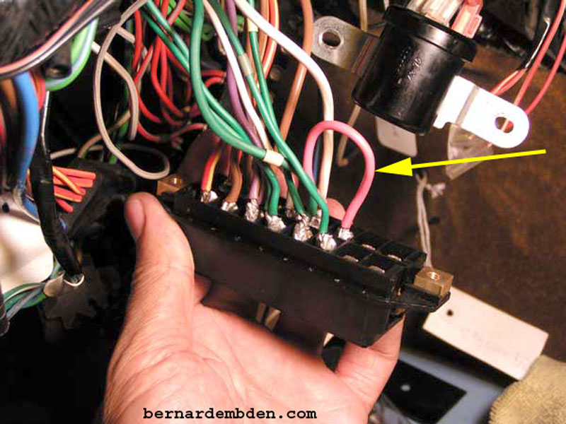
The old fuse box has an internal jumper for the power feed between fuses five and six. Duplicated this jumper on the new fuse box using a short length of wire. (yellow arrow).
Take some time to determine how the new fuse boxes will be numbered. As noted in the fabrication of this fuse panel, I wanted additional fuses so the new fuse boxes carry 8 fuses each. In order to keep the load on the fuses boxes fairly even, I split the wiring so that the first fuse box handled circuits 1 to 6. The second box would handle 1 to 12. This kept the same numbering methodology as the original, so that the fuse box cover chart would continue to be accurate.
I started the second fuse box at fuse number seven. Before connecting wires to the second fuse box, position it above or below the first box in the position they will be mounted. Once all the wires are connected the position of these fuse boxes cannot be reversed.
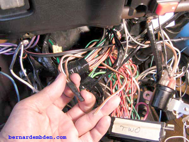
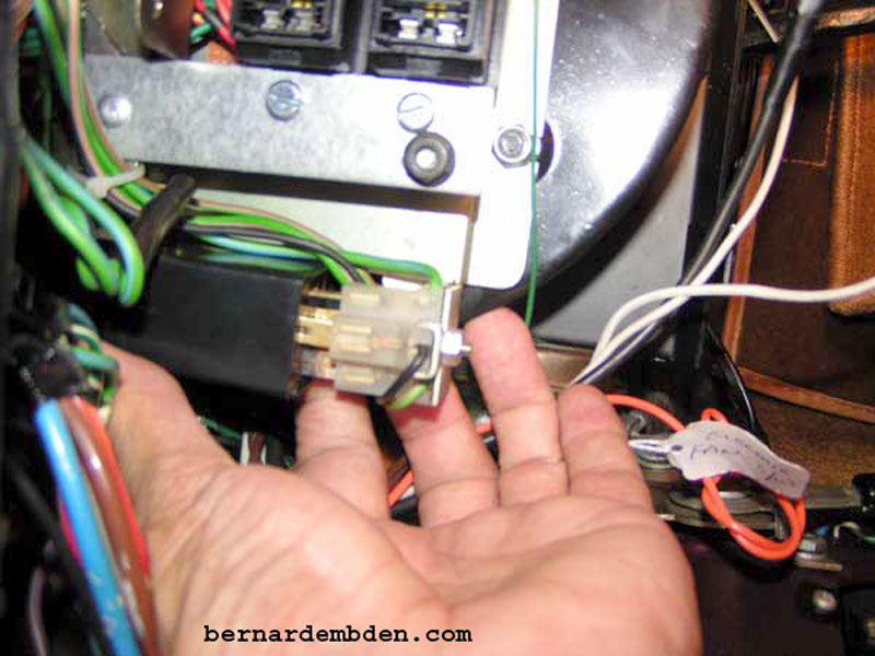
Fuse number ten is photographed below. Note that there are two wires in and out of this fuse. (light blue arrows). This is where the primary problem occurs. The load on this connection is just too much for the old barrel type glass fuse to handle.
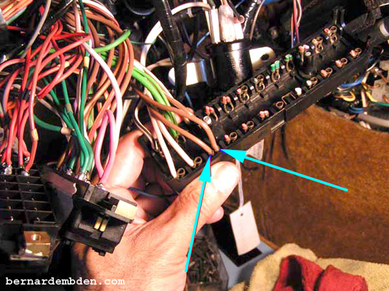
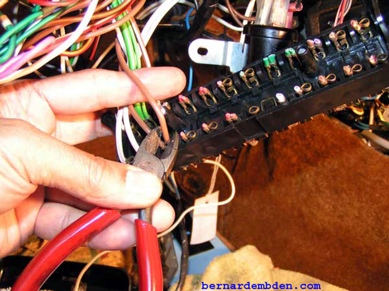
This fuse connection will be split into two fuses. Cut one power feed wire. (blue arrow) Note that I have labeled the fuse blocks one and two.
Photographed below is the source of the cut power wire from fuse number 10. The two powers feed wires at fuse number ten connect back to a single, larger wire. It's almost as if the wiring was already installed to split this one fuse connection into two fuses. The first fuse will be identified as 10A, the second as 10B.
Cut any wire from the bottom of fuse number ten and solder. Repeat for the two remaining wires and attach to the next fuse connection. These will be fuses number 10A and 10B.
New fuse blocks wiring complete. I labeled the bottom block 1-6 and the top 7-10A, 10B, 11-12.

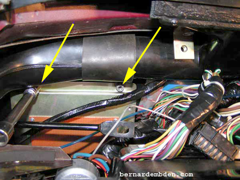
Mount the modified mounting plate from the new fuse panel to the blower motor using the original mounting studs and hardware. (yellow arrows photograph below).
Offer up the new fuse blocks to the side supports of the new fabricated fuse panel top bracket, and bolt both fuse blocks underneath the side supports.
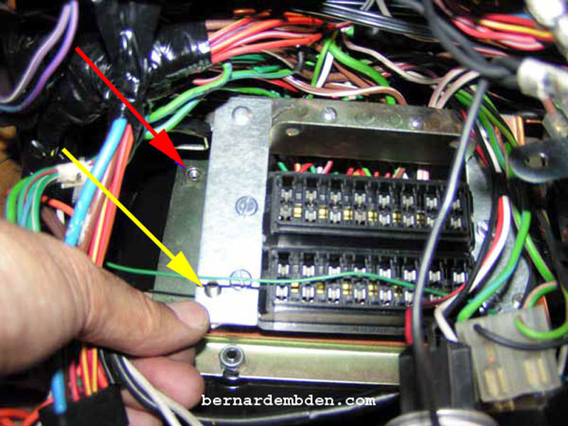
Photograph below. Position the fuse panel top bracket over the mounting plate and attach using the original screws at the top bracket. (red arrow) Use the standoff nuts to secure the bottom. (yellow arrow).
Install Ignition relay, flasher and voltage regulator back on mounting plate.
Based on the Lucas/American chart, the new ATO fuses ratings will have to be revised to properly handle the circuits they will be protecting. The chart below shows the original Lucas fuses amperage ratings, along with the new fuse amperages that I will be using. Also included is the final numbering methodology.
Install the correct fuses. First fuse, 15 AMPS for the fog lights. I labeled the bottom fuse box 1-6.
(Photograph below) The top fuse box will be 7 through 10a, 10b, 11-12, plus one additional fuse for an aftermarket relay.
These fuse boxes came with clear plastic covers. Although not necessary, I labeled the covers and attached them. Photographed below is the label for the top fuse block with fuse number ten split into 10A and 10B.
Connect wires to dashboard dimmer and install the under-scuttle.
Project complete.
Expect to spend some time on this project. It's not a difficult project, but fairly difficult to do well.
