
My 1978 XJS had developed some roughness at idle and a slight hesitation whenever the throttle was applied. If, at idle, the bell crank was moved slightly off its stop, idle would improve dramatically. Having eliminated just about everything else, I was convinced that a defective throttle switch was part of my problem.
The throttle switch is responsible for a number of functions, including sending signals to the ECU indicating an idle position, off idle position and temporary enrichment signals under acceleration.
If the throttle switch incorrectly signals the ECU, then over or under fueling in inevitable. Essentially, the correct signals sent by the throttle switch indicating idle and transition from idle to enrichment under acceleration is critical for drivability.
A deteriorating throttle switch usually occurs slowly over time and can be intermittent, making diagnosis difficult.
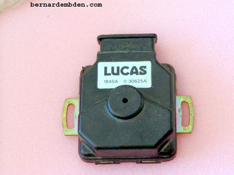
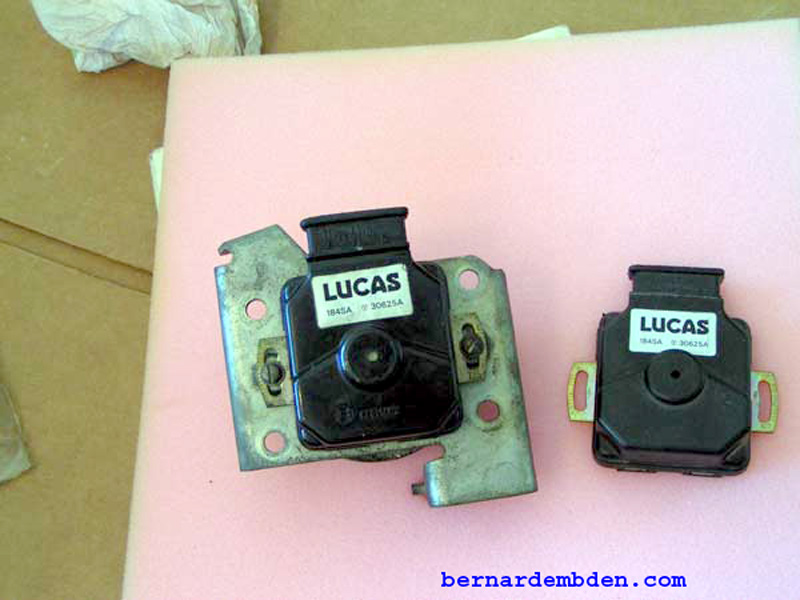
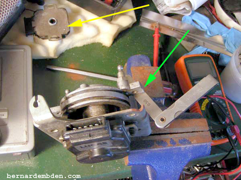
Having acquired what appears to be a fairly new unit, (Photographed below) I decided to replace the Throttle Switch.
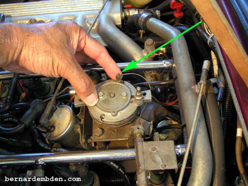
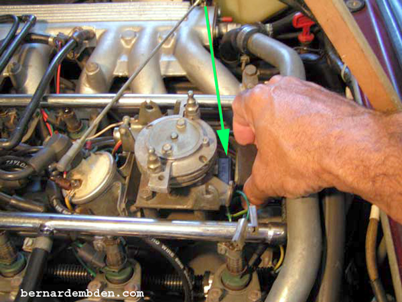
Remove bell crank throttle rods. Rotate bell crank clockwise and remove the accelerator cable from its slot. (green arrow photograph below).
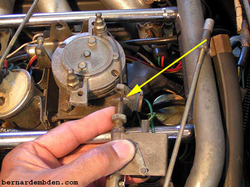
Remove nut from accelerator mounting assembly and withdraw accelerator cable through slot to remove. (yellow arrow photograph below).
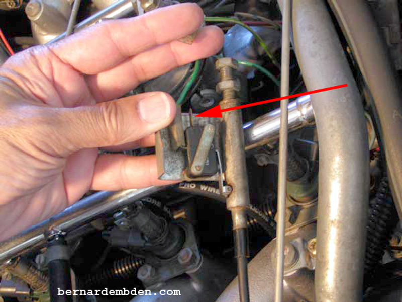
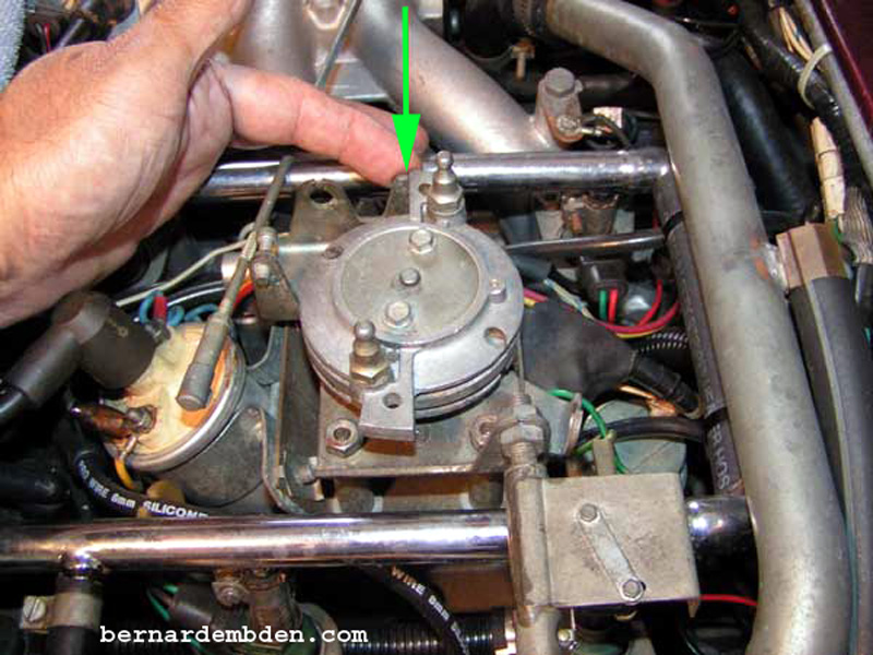
(Photograph below) Remove wires from throttle kick down micro switch. (red arrow) It's not necessary to identify these wires; they can be reconnected either way.
Remove throttle switch plug (green arrow).
Remove four nuts that hold the throttle bell crank assembly to the base pedestal.
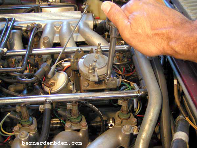
Remove throttle bell crank and switch.
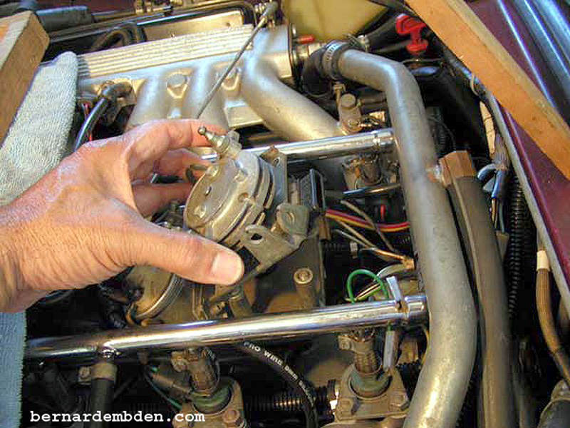
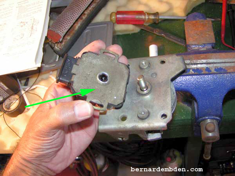
Photograph below. Note that the throttle switch is mounted to the bell crank with screws that allow the throttle switch to be adjusted. (yellow arrows).
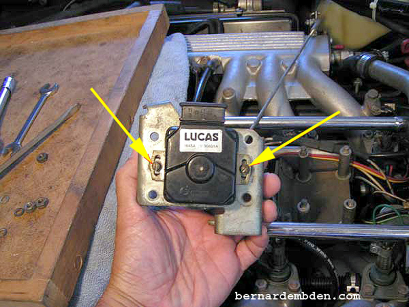
Examination of the old and replacement throttle switches indicate that the part numbers are the same.
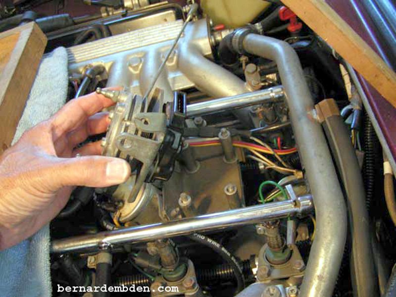
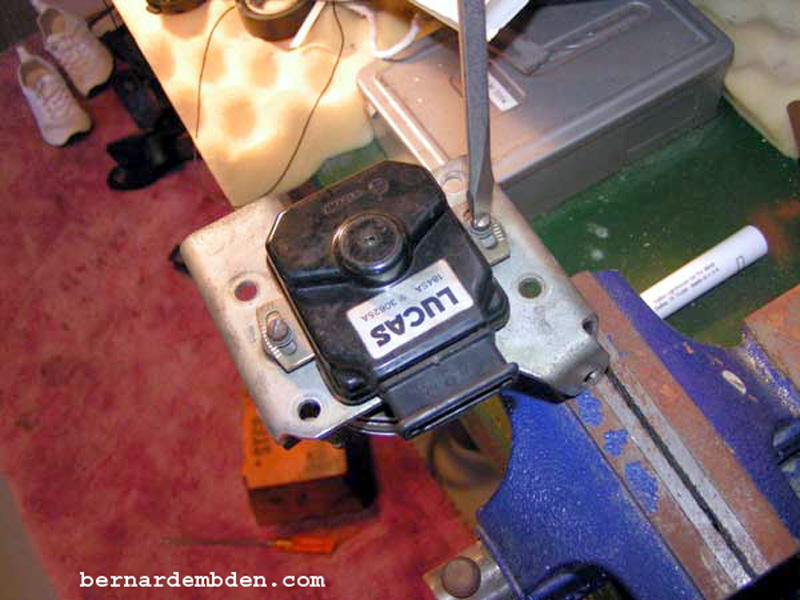
Mount the bell crank assemble in a vise and remove the two attachment screws that secures the old throttle switch.
Gently pry the throttle switch from the bell crank. Use a flat blade screwdriver if necessary.
As the throttle switch is removed, note that the direction the unit rotates is stamped on the switch body (green arrow)
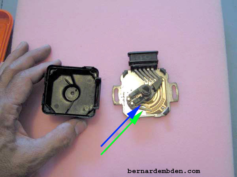
This was an opportunity for me to examine the old throttle switch. Removing the plastic cover was not difficult, and examining the inside would prove valuable in understanding what happens when it became necessary to adjust the new switch.
Photographed below is the old throttle switch with its top removed. Note the two main contact sweep assemblies. The idle (blue arrow) and the accelerator enrichment (green arrow) The switch is currently in the "idle" position.
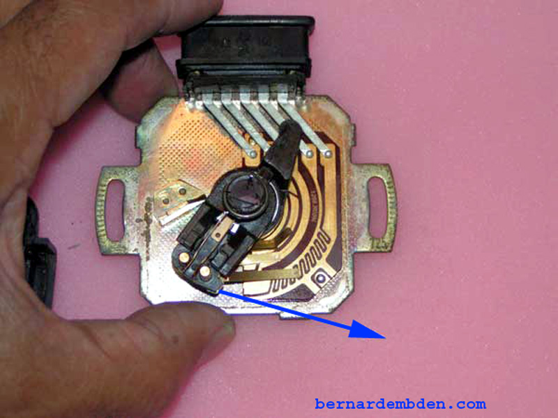
Note position of the two sweep contacts (green and blue arrows in above photograph) as the throttle switch is rotated counter-clockwise, simulating accelerator off idle movement. (blue arrow photograph below).
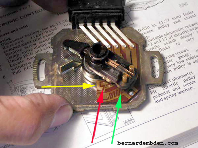
Closer look at the throttle switch at full rotation reveals the following in the photographed below:
Yellow arrow. The idle sweep contact. The first contact is the position at idle, bell crank against throttle stop. This provides a short circuit between terminals 12/47 and terminal 17.
Red arrow. As the throttle switch moves off idle the short circuit become an open circuit (space between contacts). This represents the .050 inch adjustment of the bell crank.
Green arrow. The enrichment contact sweep. As the throttle switch rotates it provides alternately closed and open conditions between terminals 12/47 and terminal 9.
Mount the replacement throttle switch onto the bell crank. (old throttle switch yellow arrow) Do not tighten the adjustment screws. Insert a 050-inch feeler gauge between bell crank pulley and closed throttle stop. (green arrow photograph below).
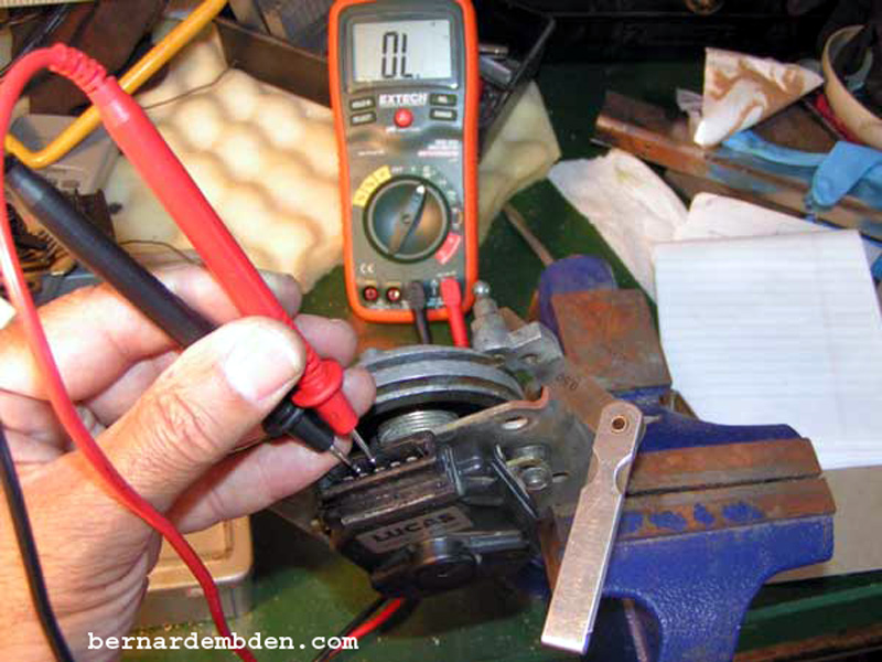
(Photograph below) Rotate the throttle switch until it just moves the bell crank off its stop, then reverse rotation until the bell crank just touches the stop. Using a voltmeter or tester connect to terminals 12/47 and 17. Rotate throttle switch slowly until a short is indicated by the tester. Remove feeler gauge. Tester should now record an open circuit. Tighten adjustment screws. Retest with feeler gauge and remove. Final tighten adjustment screws. Make sure the bell crank turns freely without binding. Connect tester between terminals 12/47 and terminal 9. Rotate throttle switch slowly through it's full range. Tester should indicate alternate ten (10) open and closed circuits.
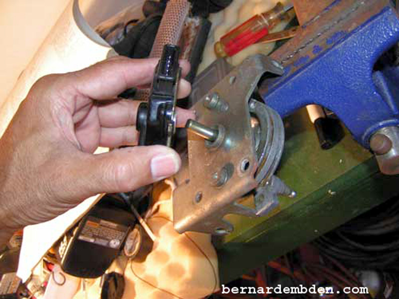
Offer bell crank and replacement throttle switch to mounting pedestal and tighten four attachment nuts. Connect wires to throttle kick down micro switch (yellow arrow).

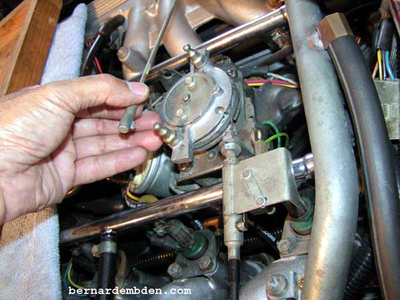
Make sure accelerator cable allows bell crank to fully rest against throttle stop (green arrow photograph below).
Install bell crank throttle rods. They should install without the bell crank moving off the throttle stop. Adjust throttle rods if necessary.
Not a difficult job, however proper adjustment of the replacement throttle switch prior to final assembly is critical.
