
I started to have a problem with my AC system running after the switch was turned off. Soon after I noticed that the auxiliary radiator electric fan would run continuously once the car was switched on. Initial diagnosis indicated that 12 volts were being fed to the electric fan relay the moment the ignition switch was activated.
This symptom is typical of a failed diode. However, unlike the "HE" cars, there is no "Darling" resistor pack in the blower motors of the Pre-HE models. Rather it appears that the diode or diodes controlling current flow to the HVAC blowers and electric fan are integrated somewhere within the wiring harness.
Unable to find the failed diode, I determined that another solution was called for.
The saga of searching for these diodes is detailed in another link on this website.
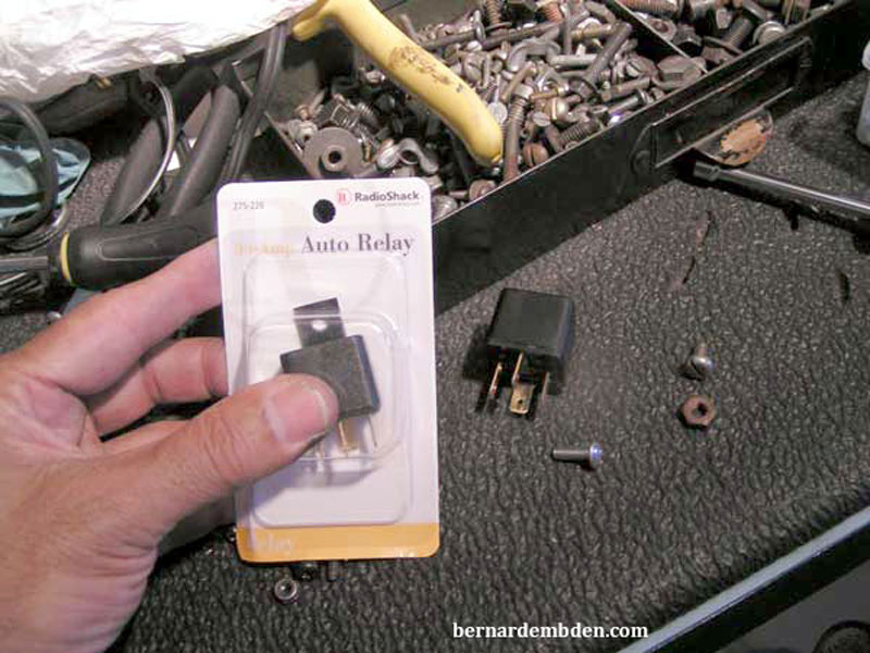
The project starts by securing three 4 contact, normally open, relays. One 40 amp and two 30 amp. I found the 30 amp units at Radio Shack and the 40 amp at AutoZone, two electronics and automotive chains in the US.
Next, open the wiring harness that feeds the electric fan relay on the left fender. The fan relay is activated in two separate modes.
1) By a thermostatic switch installed in the water pump inlet that monitors incoming water temperature.
2) By the HVAC system that activates the fan relay whenever the AC compressor is turned on.
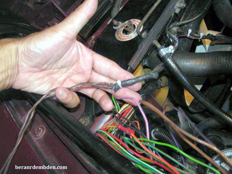
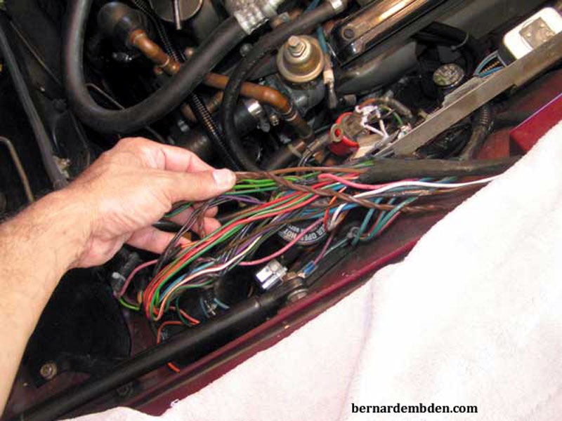
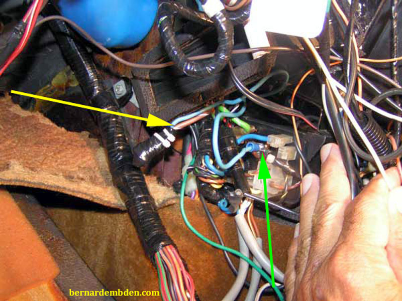
Within the wiring harness, trace the green/brown wire from the fan relay back to the 3 green/brown wire connection. Identify and cut the wire that goes back to the HVAC system. This is the only wire going back towards the engine cowl. (white arrows photographs below).
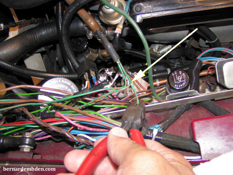
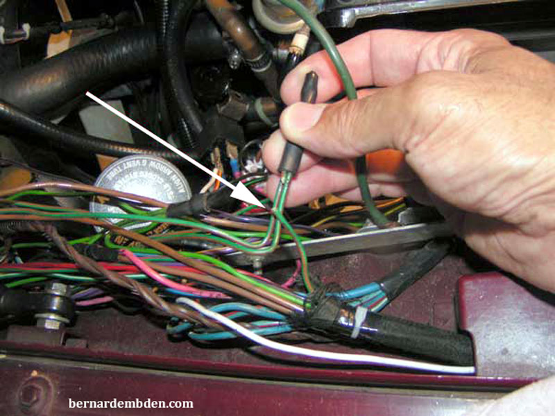
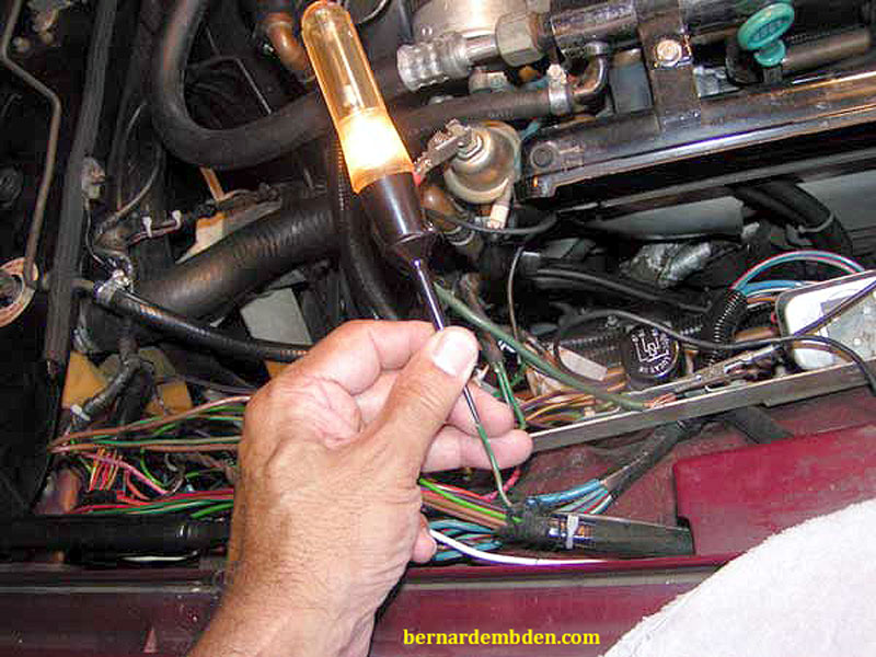
A test light (photograph below) verifies 12 volts at this wire with the ignition on. This is the feedback voltage that is activating the fan. Note that with this wire cut the water temperature sensor will still activate the fan, however the HVAC system will not.
This fan will now be operated by one of the 30 amp relays via a switch on the dashboard. Of course there is a small problem. With the wire going back to the HVAC system cut, the HVAC system in the cooling mode will activate the AC compressor. The electric fan will not come on. In order for this to work intuitively, the compressor also has to be activated by the same switch.
This is why we need two 30 amp relays.
The second 30 amp relay will activate the AC compressor.
A note of caution. The current paths needs to be kept separate.
Bridge the two wires going to the electric fan's thermostatic switch in the water pump. (The inline fuse to the electric fan has been moved to a new fuse panel on the inner fender).
Connect these two wires to a normally open 30-amp relay that will close the two wire contacts when it sees 12 volts. Essentially you are activating the thermostatic switch to turn on the electric fan. A simple switch could be used here, however the relay is needed to keep the two connections completely separate.
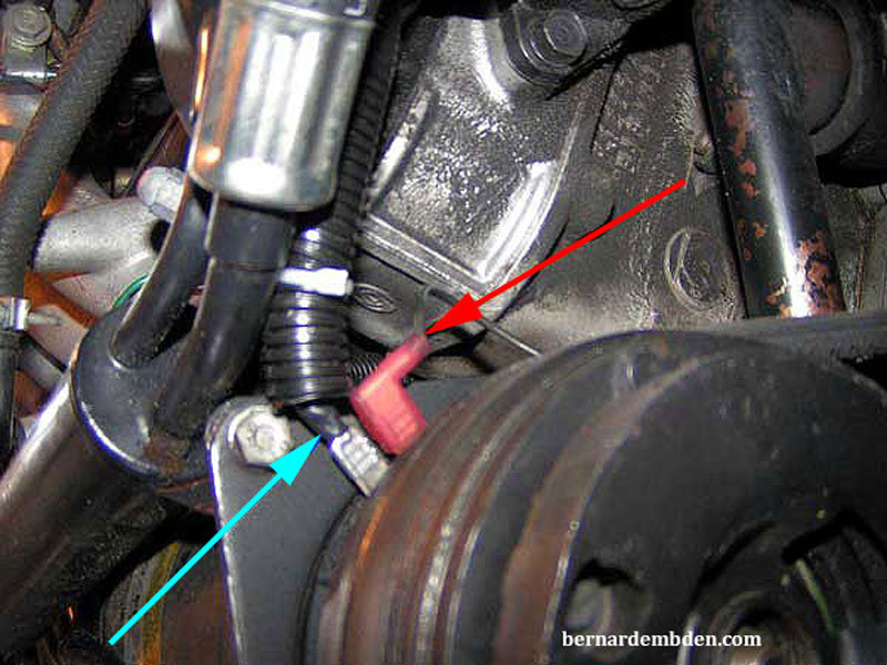
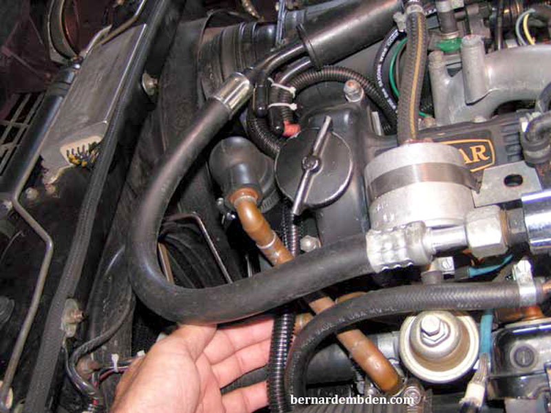
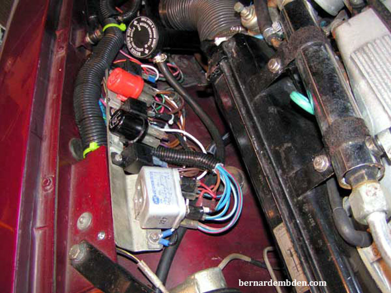
Next is the AC compressor. (photograph below) One connection (red arrow) grounds the coil. Remove the 12-volt feed wire from the AC compressor coil assembly and install a new wire. Solder and heat shrink the proper size spade connection. (light blue arrow).
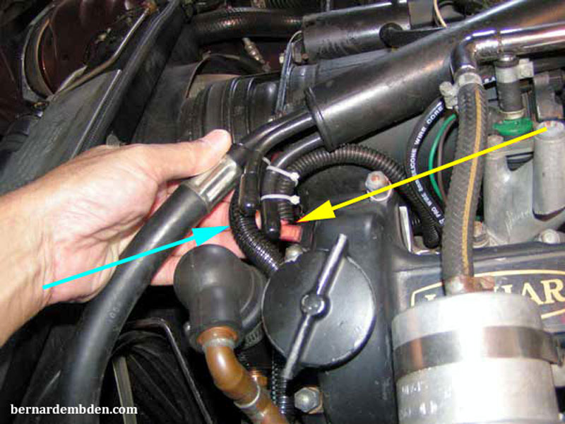
These engines will melt regular wire insulation. Do not allow the wire to just lie around and come in contact with the engine. Photographed below is the new feed wire, protected by heat resistant wiring loom. (light blue arrow) Don't just leave the old connection flopping around. Secure and tie-wrap the old connection. (yellow arrow).
Route new 12-volt feed wire back to the relay location.
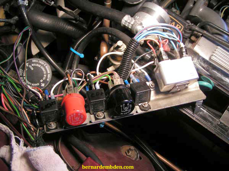
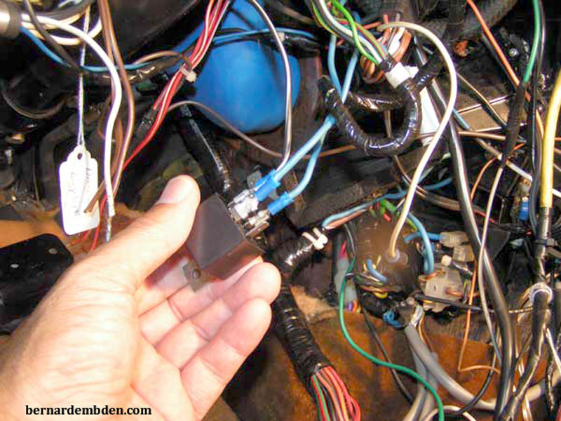
(Photograph below) All my relays had been moved to the inner fender on a prior project. I mounted the two additional relays on the modified relay bracket. The 12 volts needed for this relay was sourced from the horn relay's 12-volt input. Another option is to bridge off the buss bar. If you choose this method, be sure to install an inline fuse.
The 12 volts to the switch MUST come off the "ignition on" relay, otherwise you could send 12 volts to the A/C compressor coil with the engine off.
Below is a hand drawn schematic of the switch and relays. Note that one relay closes the two wires bridged to the thermostatic switch, while the other relay sends 12 volts to the A/C magnetic coil assembly..
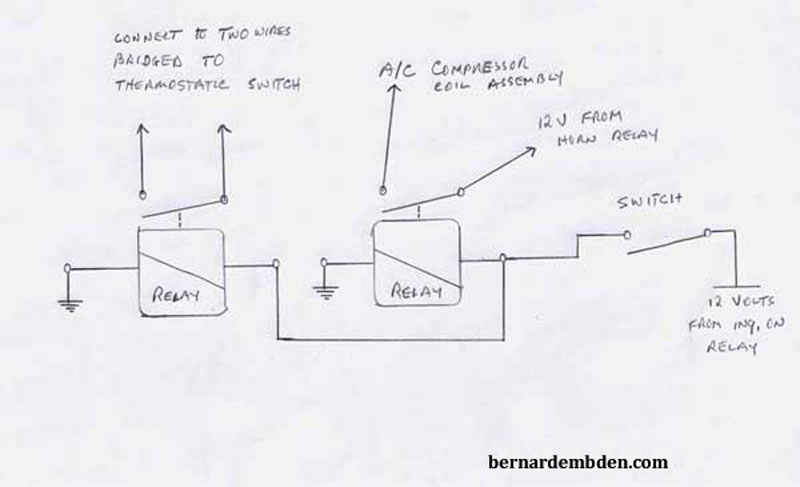
Normally I like to have the switch send ground (not 12 volts) to the relays. In this case I needed 12 volts at the switches to activate "Switch on" light indicators.
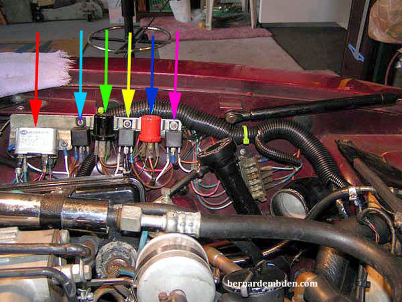
I mounted all the relays on the inner fender, photographs below.
Red arrow. Headlight relay
Light Blue arrow. New, Thermostatic switch "fan on" relay.
Green arrow. Horn relay.
Yellow arrow. New, Compressor magnetic clutch relay.
Dark Blue arrow. Electric fan relay.
Pink arrow. New, Fog light relay. (prior project)
The second part of this project is to address the blower fans that seem to have a life of its own. They would, on occasion continue to run even after the AC switch was turned to the "off" position.
Start by locating the brown/white wire that feeds the AC blower relay, mounted at the left side of the console, behind the kick panel. This is the same wire that feeds off the problematic 50 amp fuse.
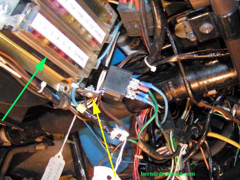
(Photograph below) Remove this wire from the AC blower relay. Lengthen this wire so that it can connect to one side of the 40-amp relay. (yellow arrow). Connect the other relay connection to the post on the AC relay that the brown/white wire came off. (green arrow).
Crimp or solder the correct spade connections to the wires and attach to the relay. Note: The wire must be at least the same size and rating at the original brown/white wire. It must be rated for a minimum of 30 amps US.
(Photograph below) I made a small bracket and mounted the relay below the fuse panel. (yellow arrow) This relay, normally off, will cut all power to the main A/C relay. It will be activated by a separate switch mounted on the dashboard. Note new fuse panel (green arrow).
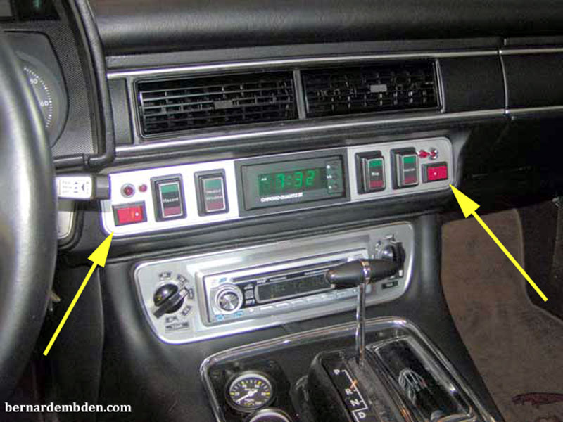
Photographed below are the two switches installed in the dashboard. (yellow arrows). The left switch operates the two relays that activates the auxiliary electric fan and the A/C compressor's magnetic coil. The switch on the right activates the 40-amp relay mounted below the fuse panel. This relay provides power to the A/C relay mounted under the left side kick panel.
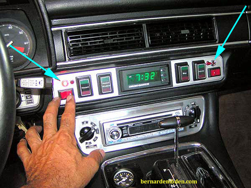
Each switch has its own indicator light that is activated whenever any of the switches are turned on. (light blue arrows photograph below).
This project is completed, however it's a temporary project. For owners of old vintage cars the work is never done. The search for the failed diodes continues.
